Strip till control: servo control valve, Strip till control: auxiliary tab” on page 262 – Ag Leader Versa Users Manual User Manual
Page 266
252
Firmware Version 5.4
Press: Home button > Setup (wrench) button > Configuration (tractor) button > Configuration tab > select
your specific configuration > Setup (wrench) button >Controller Settings button
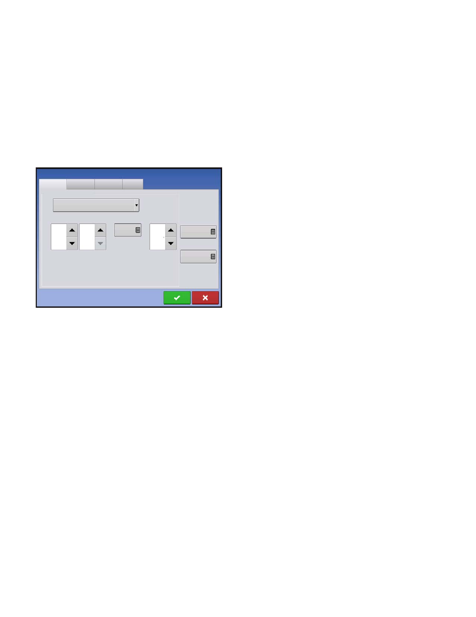
Controller Settings screen appears, with each channel’s settings shown on its own tab.
Controller settings viewed at the Strip Till Control window vary depending on Control Valve Configuration
type selected including PWM Control Valve, a Servo Control Valve, or a Linear Actuator configuration.
Use the Control Valve Configuration drop-down menu to choose the appropriate configuration for your
machine. Control valve configuration settings are described in the following section. The Auxiliary Tab
allows for adjusting fan settings described at
“Strip Till Control: Auxiliary Tab” on page 262
Strip Till Control: Servo Control Valve
• Valve Response 1
Determines the speed of the servo valve when product
control error exceeds the Response Threshold setting.
Represents the fast speed of the servo valve.
Decreasing the value will cause the servo valve to run
slower. The default setting is 40%.
• Valve Response 2
Determines the speed of the servo valve when product
control error is less than the Response Threshold
setting. Represents the slow speed of the servo valve.
Decreasing the value will cause the servo valve to run
slower. The default setting is 8%.
• Response Threshold
Determines where the control channel switches between using Valve Response 1 and Valve Response 2
speed setting. Leaving all other valve control settings at the default value and making a small adjustment
to this setting is usually all that is required to fine tune system performance. The default setting is 15.
- Decreasing this value will have the overall effect of speeding up servo valve response.
- Increasing this value will have the overall effect of slowing servo valve response.
• Allowable Error
Determines the percent of error that is allowed prior to the product control system making any flow rate
changes. 2% - 3% is the normal dead band setting range.
- Too low of a setting value can cause the product control system to continually hunt for the target
application rate.
- Too high of a setting will cause excessive product application error.
• Shaft Speed Calibration
Calibration number representing the pulses that equal one revolution of the rate control metering system.
• Max Metering Speed
Setting determines the maximum RPM of the metering shaft that controls product distribution to the
application point. This setting is used when controlling a granular strip-till toolbar.
Channel 1
Channel 2
Channel 3
Auxiliary
Control Valve Configuration
Servo
Valve
Response 1
Valve
Response 2
Response
Threshold
Allowable
Error
40 %
8 %
15
2 %
Shaft Speed
Calibration
180 pls/rev
Max Metering
Speed
100 rpm
Strip Till Control