Strip till control: pwm control valve, Linear actuator/clutch settings, Pplication – Ag Leader Versa Users Manual User Manual
Page 267: Trip
253
A
PPLICATION
S
TRIP
T
ILL
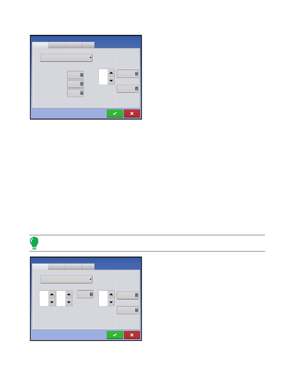
Strip Till Control: PWM Control Valve
• PWM Frequency
The frequency that the PWM control valve is pulsed at.
Settings can be found from the manufacturer of the
valve. Typical settings range from 100-125 Hz. The
default setting is 100.
• PWM Gain
Determines how aggressively the control valve responds
when making rate changes. The higher the value the
more aggressive the system response is. The default
setting is 100.
• Zero Flow Offset
Represents the maximum duty cycle that is sent to the
control valve without producing any hydraulic flow from
the PWM valve. Using too high of a Zero RPM Offset value can cause the conveyor to not properly shut off.
See the PWM valve manufacturer information for recommended settings. The default setting is 30.
• Allowable Error
Determines the percent of error that is allowed prior to the product control system making any flow rate
changes. 2% - 3% is the normal dead band setting range.
- Too low of a setting value can cause the product control system to continually hunt for the target
application rate.
- Too high of a setting will cause excessive product application error.
• Shaft Speed Calibration
Calibration number representing the pulses that equal one revolution of the rate control metering system.
• Max Metering Speed
Setting determines the maximum RPM of the metering shaft that controls product distribution to the
application point. This setting is used when controlling a granular strip-till toolbar.
Linear Actuator/Clutch Settings
Note: When using Linear Actuator Control, the system requires the Control Valve Configuration on all three
channels to be set the same.
• Actuator Response 1
Determines the speed of the actuator when product
control error exceeds the Response Threshold setting.
Represents the fast speed of the actuator. Decreasing
the value will cause the actuator to run slower. The
default setting is 90%.
• Actuator Response 2
Determines the speed of the actuator when product
control error is less than the Response Threshold
setting. Represents the slow speed of the actuator.
Decreasing the value will cause the actuator to run
slower. The default setting is 18%.
Strip Till Control
Channel 1
Channel 2
Channel 3
Auxiliary
Control Valve Configuration
PWM
PWM Frequency
100
PWM Gain
100
Zero Flow Offset
30
Allowable
Error
2 %
Shaft Speed
Calibration
180 pls/rev
Max Metering
Speed
100 rpm
Strip Till Control
Channel 1
Channel 2
Channel 3
Auxiliary
Control Valve Configuration
Single Bin Actuator
Allowable
Error
2 %
Shaft Speed
Calibration
180 pls/rev
Max Metering
Speed
100 rpm
Actuator
Response 1
90 %
Actuator
Response 2
18 %
Response
Threshold
4