Fence row nozzle indicators, Load configuration, Run configuration – Ag Leader Versa Users Manual User Manual
Page 199: Ence, Ozzle, Ndicators, Onfiguration
185
A
PPLICATION
L
IQU
ID
R
ATE
C
ONTROL
F
ENCE
R
OW
N
OZZLE
I
NDICATORS
Control fence row nozzles through the DirectCommand system by mapping the switches in Auxiliary
Input Settings. Fence row nozzles can be mapped to any switch.
or
Press: Home button > Setup (wrench) button > Configuration (tractor) button > Configuration tab > select
your specific configuration > Setup (wrench) button > Auxiliary Input button > Assign button > Left Fence
Row or Right Fence Row. For more information on Auxiliary Input Settings, see
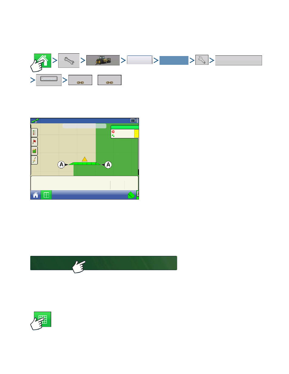
After specifying Fence Row Nozzle settings at the
Auxiliary Input Assignment screen, the Fence Row
Nozzle Indicators (A), which are shaped like
triangles, appear on either side of the sections behind
the vehicle icon.
Notes:
If a switch is selected as a Left or Right Fence Row Nozzle, the system sends power out of Boom Pin 11
for the left fence row, and Boom Pin 12 for the right fence row.
The boom sections next to the fence row nozzles must be turned on before the fence row nozzle can be
turned on.
L
OAD
C
ONFIGURATION
Press: Select Event button.
Select a Season, Grower, Farm, and
Field on the Management Selection
screen.
For more information, see
R
UN
C
ONFIGURATION
Once a configuration has been completed, the Map View button appears at the bottom of the
Home screen. Press the Map View button to see the Map screen. The map below is displayed
in Zoom to Detail view.
Configuration
Select Your Specific
Configuration
Auxiliary Input
Assign
Left Fence Row
Right Fence Row
20
20
41
43
47
Pressure (PSI)
fl oz/ac
5.0
mph
38.4
ac
Main
Auxiliary
Agitation
Valmax
Select Event