Liquid application diagnostics, Troubleshooting directcommand liquid applications, Iquid – Ag Leader Versa Users Manual User Manual
Page 207: Pplication, Iagnostics, Roubleshooting, Irect, Ommand, Pplications
193
A
PPLICATION
L
IQU
ID
R
ATE
C
ONTROL
CAUTION: Selection of the wrong data column or unit will result in misapplication of product.
Note: The only time the default rate is used by the system during product application is if the Rate Outside of
Field selection is set to " Rx default". This setting is located in the equipment configuration settings portion of
configuration setup. If the Rate Outside of Field selection is set to "Rx default", the default target rate will be
used when the vehicle exits the area covered in the prescription map.
L
IQUID
A
PPLICATION
D
IAGNOSTICS
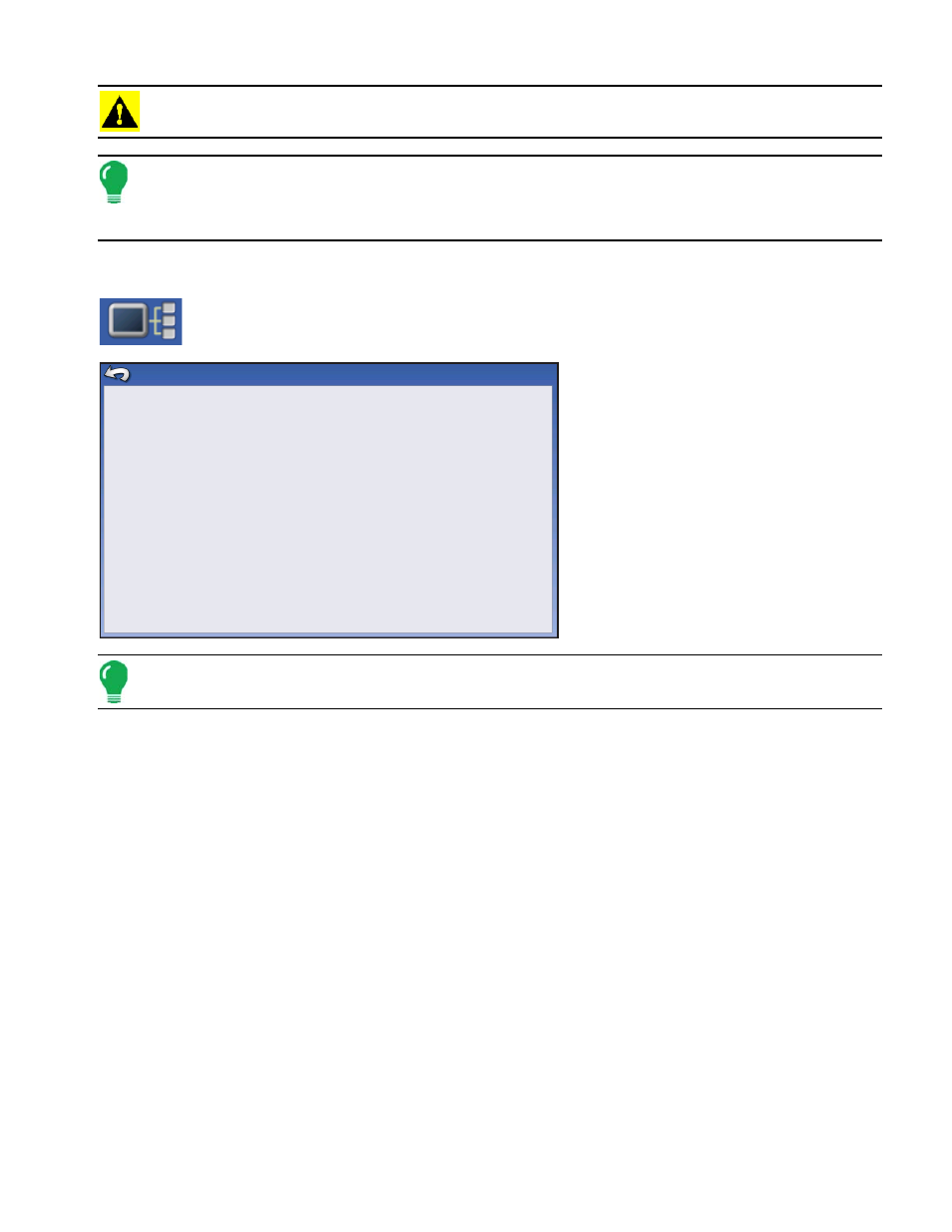
To go to the Liquid Diagnostics screen, press on the Device Information button. At the
Devices screen, highlight the item marked DC Liquid then press the Diagnostics button.
The Liquid Diagnostics screen includes
the Active Controller Name and the
Serial Number of the module. Other
information provided includes the Main
Pressure, Agitation Pressure, and
Auxiliary Pressure. These raw sensor
readings are shown in kilopascals (kPa).
Note: If you selected PWM as the Control Valve then the current PWM Duty Cycle is shown as a percentage
number, in the PWM Duty Cycle (%) item on the Liquid Diagnostic screen.
• Flow Meter Signal Frequency (Hz)
View the frequency generated by the flow meter during product application. Use this to make sure the flow
meter is providing continuous feedback.
• Flow Meter Pulse Count
provides a rolling count of pulses generated from the flow meter during product application. This diagnostic
item can be used to easily check that the flow meter is providing feedback to the system and also provides
a way to check flow meter cabling without changing settings within the system setup.
T
ROUBLESHOOTING
D
IRECT
C
OMMAND
L
IQUID
A
PPLICATIONS
Problem: Boom indicators on the run screen of the display do not turn green.
Solution:
1. Make sure ground speed is registering a value greater than zero on the display.
2. Verify a target rate greater than zero is entered into the display.
3. Check the switch status found on the Run screen under System and Input Diagnostics. As the
boom switches are turned on and off, the Input Diagnostics window should change from black
to green (if they do not, then refer to the installation instructions to verify boom switch
connections).
4. Check high current connection into the Liquid Control Module.
Controller Name
Serial Number
Main Pressure (kPa)
Agitation Pressure (kPa)
Auxiliary Pressure (kPa)
PWM Duty Cycle (%)
Flow Meter Signal Frequency (Hz)
Fow Meter Pulse Count
DirectLiquid
2003750001
738
662
655
2.55
0
0
Liquid Diagnostics