High availability features, Operator control panel, Hsv110 controller—front and rear views – HP 3000 Enterprise Virtual Array User Manual
Page 94
CXO8040A
Front
Rear
1
2
9
10
8
7
6
5
4
3
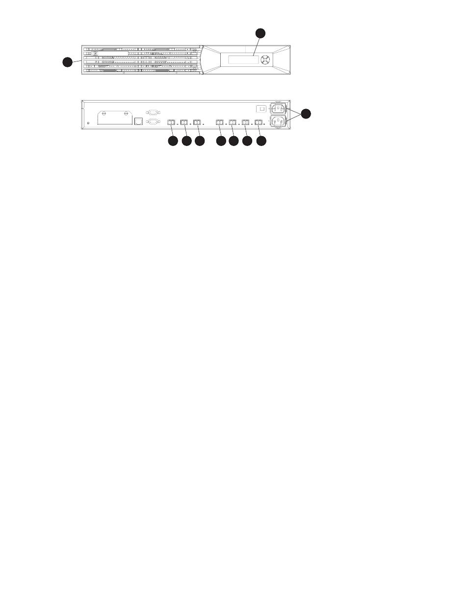
Figure 44 HSV110 controller—front and rear views
1.
Bezel
2.
OCP
3.
HF1 port
4.
HF2 port
5.
Mirror port
6.
1B port
7.
2B port
8.
1A port
9.
2A port
10.
Power input
High availability features
Two interconnected controllers ensures that the failure of a controller element (such as a power supply,
transceiver, fiber optic or copper Fibre Channel cable, Fibre Channel port, and so forth) does not disable
the system. For EVA5000 configurations, the complete data redundancy configuration includes two
Loop A and two Loop B data paths. For EVA3000 configurations, data redundancy is accomplished
with two Loop A data paths.
A single controller can fully support an entire system until the defective controller, or controller element,
is repaired.
If a
blower
fails, it can be replaced without shutting down the system.
Each HSV110 controller has two lead-acid cache battery assemblies that provide power to the cache
memory dual in-line memory modules (DIMMs). Each battery assembly has three lead-acid, nonspillable
cells. When both battery assemblies are fully charged, they can provide power to the DIMMs for up to
96 hours.
Operator control panel
The OCP (see
) is an interface between you and the controller. Much of the information provided
here duplicates information displayed on the Command View EVA graphical user interface (GUI). Even if
you cannot observe the GUI, or if the GUI is not functioning, the controller status is available on the OCP.
You can use the OCP LEDs, the LCD, and the push-buttons to determine the controller status.
The OCP displays system information (status and error conditions) and lets you enter data or isolate
problems.
94
Storage system hardware components