Dual pdu assembly—top view – HP 3000 Enterprise Virtual Array User Manual
Page 106
•
The standard 50-Hz PDU cable has an IEC 309, 3-wire, 30-A, 50-Hz connector.
•
The standard 60-Hz PDU cable has a NEMA L6-30P, 3-wire, 30-A, 60-Hz connector.
If these connectors are not compatible with the site power distribution, you must replace the PDU power
cord cable connector.
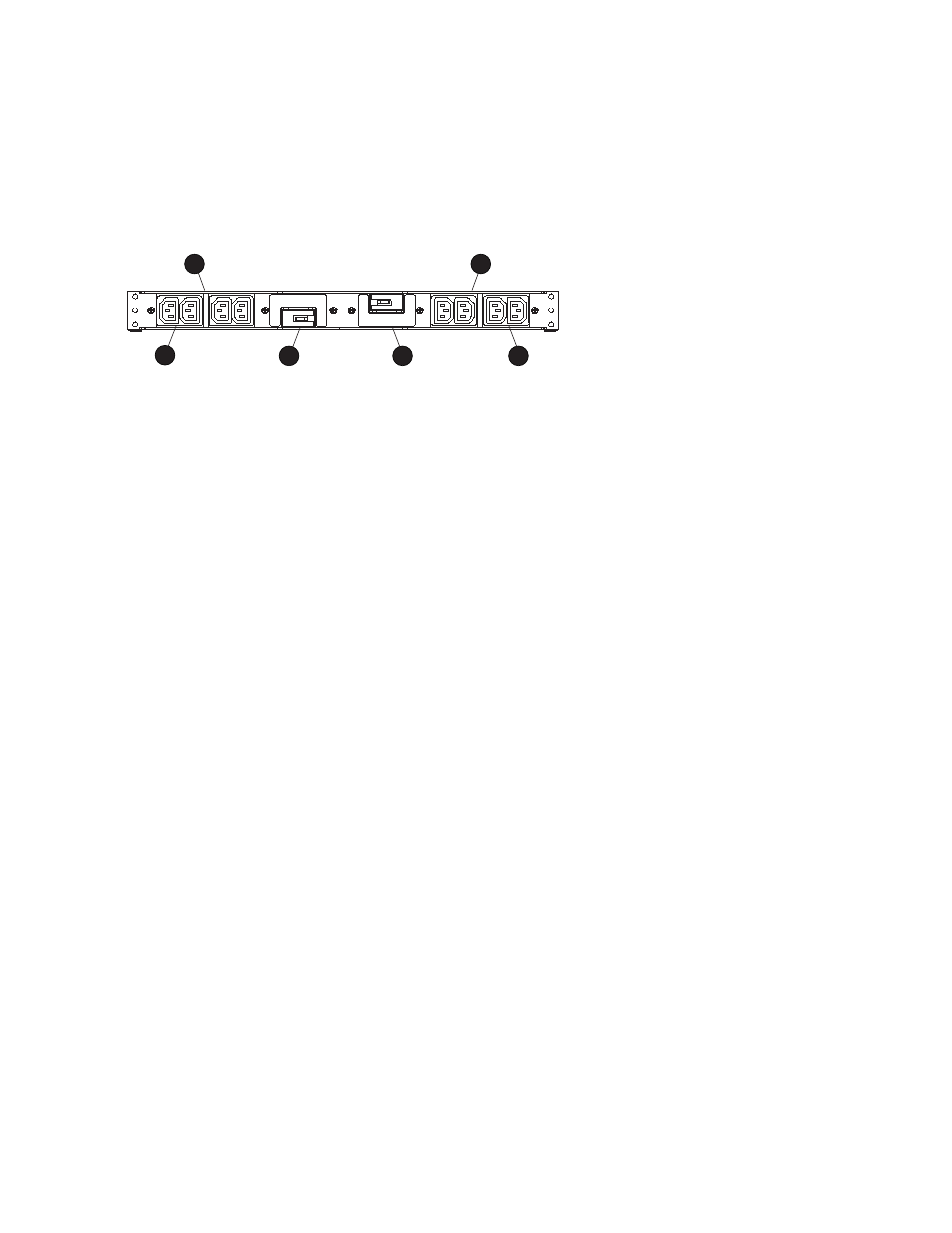
Each of the two PDU power cables has an AC power source specific connector. The
circuit-breaker-controlled PDU outputs are routed to a group of four AC receptacles (see
). The
voltages are then routed to PDMs, sometimes referred to as AC power strips, mounted on the two vertical
rails in the rear of the rack.
CXO7570A
1
4
2
3
5
6
Figure 50 Dual PDU assembly—top view
1.
PDU 1
2.
PDU 1 AC receptacles
3.
PDU 1 circuit breaker
4.
PDU 2
5.
PDU 2 AC receptacles
6.
PDU 2 circuit breaker
PDU 1
PDU 1 connects to AC power distribution source 1. A PDU 1 failure:
•
Disables the power distribution circuit.
•
Removes power from PDMs 1, 2, 3, and 4.
•
Disables PS 1 in the drive enclosures.
•
Disables the upper controller power supply.
PDU 2
PDU 2 connects to AC power distribution source 2. A PDU 2 failure:
•
Disables the power distribution circuit.
•
Removes power from PDMs 5, 6, 7, and 8.
•
Disables PS 2 in the drive enclosures.
•
Disables the lower controller power supply.
PDU assembly
The dual PDU assembly (see
) mounts in the lower rear of the rack. This assembly contains two
PDUs: PDU 1 and PDU 2 . Each PDU has a 250-VAC, 30-A circuit breaker (6 and 12) and four IEC
320-C13 AC output power receptacles (2 through 5, and 8 through 11). The circuit breakers and AC
receptacles are accessible when the PDU assembly is in the upright position.
106
Storage system hardware components