Controls and displays, Emu location, Emu controls and displays – HP 3000 Enterprise Virtual Array User Manual
Page 71: Figure 32
CXO7971A
1
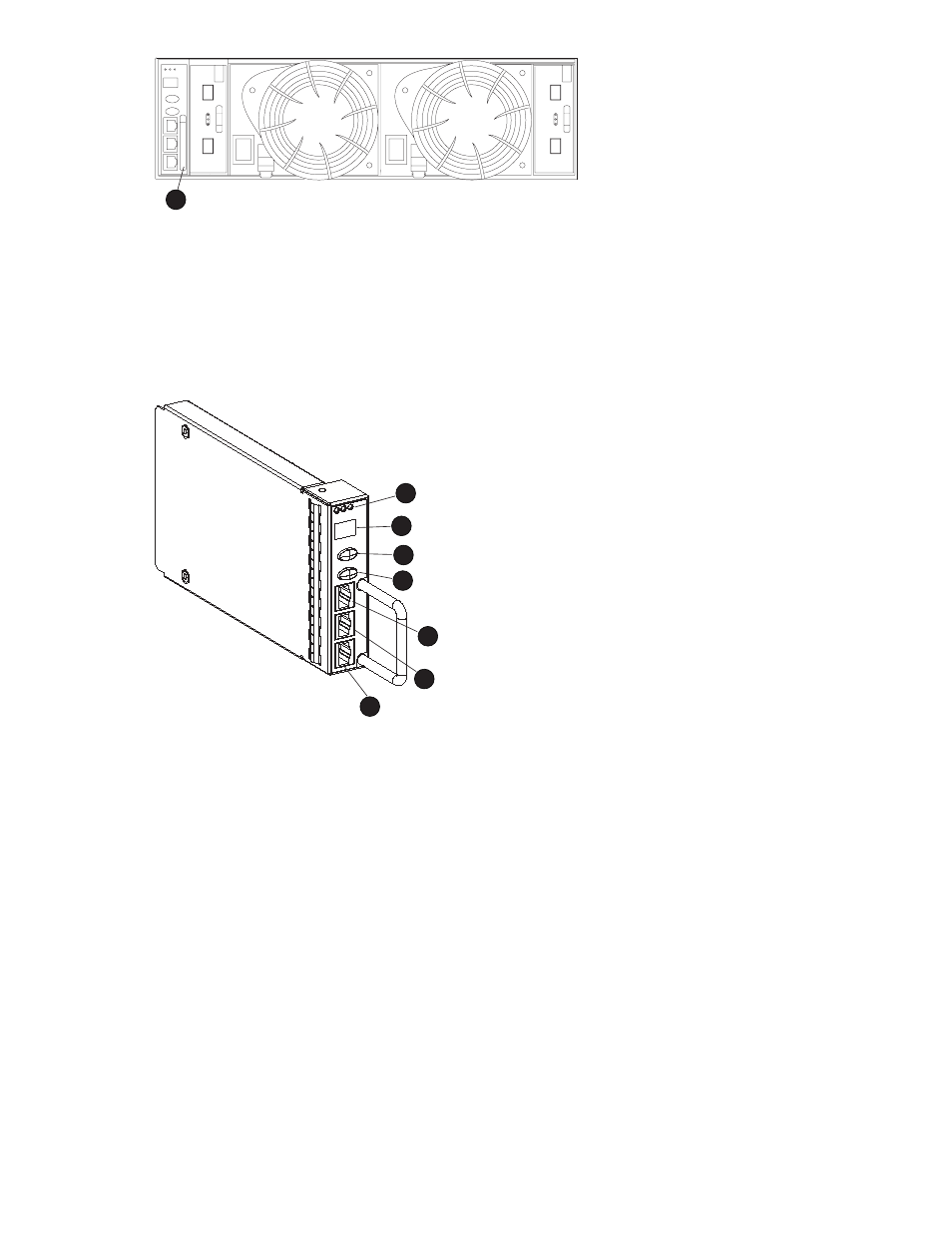
Figure 32 EMU location
1.
EMU
Controls and displays
identifies the location and function of the EMU displays, controls, and connectors.
CXO6709A
3
1
2
4
5
6
7
Figure 33 EMU controls and displays
1.
Status LEDs
These 3 LEDs display the EMU and enclosure status.
2.
Alphanumeric display
A 2–character, 7–segment alphanumeric display of the enclosure functions and status.
3.
Function Select (top) push-button
The primary function of this push-button is to select a display group function. The LED is on when an
error condition exists.
4.
Display Group Select (bottom) push-button
This push-button is used to view display groups and control the audible alarm. The LED is on when
the audible alarm is muted or disabled.
5.
RS232 ONLY–A keyed, RJ45-type connector for use by HP Authorized Service Representatives.
6.
LCD ONLY–An unused RJ45-type connector.
7.
CAB ONLY–A keyed, RJ45-type enclosed address bus connector.
Enterprise Virtual Array 3000/5000 user guide (VCS 3.110)
71
- StorageWorks MSL6000 Tape Library (61 pages)
- Лент-е накопители HP StoreEver DAT (64 pages)
- Лент-е накопители HP StoreEver DAT (50 pages)
- StoreEver Ultrium Tape Drives (75 pages)
- StoreEver Ultrium Tape Drives (60 pages)
- Linear Tape File System Software (28 pages)
- Linear Tape File System Software (25 pages)
- StoreEver Ultrium Tape Drives (78 pages)
- StoreEver Ultrium Tape Drives (76 pages)
- Linear Tape File System Software (20 pages)
- StoreEver Ultrium Tape Drives (61 pages)
- StoreEver TapeAssure Software (40 pages)
- 2600fx Optical Disk Drive (65 pages)
- Ленточный автозагрузчик HP StorageWorks DAT 72x10 (58 pages)
- StorageWorks 1500cs Modular Smart Array (71 pages)
- 2000fc Modular Smart Array (150 pages)
- StorageWorks 1000 Modular Smart Array (72 pages)
- StorageWorks 1000 Modular Smart Array (81 pages)
- StorageWorks 1500cs Modular Smart Array (48 pages)
- StorageWorks 1500cs Modular Smart Array (52 pages)
- Servidor de almacenamiento HP ProLiant DL585 G2 (152 pages)
- Sistemas de almacenamiento de red HP StorageWorks X3000 (152 pages)
- Software de HP StoreVirtual VSA (85 pages)
- Software de HP StoreVirtual VSA (127 pages)
- X500 Data Vault (331 pages)
- StorageWorks 1000i Virtual Library System (122 pages)
- StorageWorks XP Remote Web Console Software (20 pages)
- 200 Storage Virtualization System (176 pages)
- XP Array Manager Software (101 pages)
- StorageWorks MSA 2.8 SAN Switch (22 pages)
- StorageWorks MSA 2.8 SAN Switch (104 pages)
- StorageWorks MSA 2.8 SAN Switch (270 pages)
- StorageWorks MSA 2.8 SAN Switch (307 pages)
- StorageWorks All-in-One SB600c Storage Blade (72 pages)
- StorageWorks All-in-One SB600c Storage Blade (80 pages)
- StorageWorks All-in-One SB600c Storage Blade (78 pages)
- StorageWorks All-in-One SB600c Storage Blade (60 pages)
- ProLiant DL585 G2 Storage-Server (150 pages)
- Data Protector Express Basic-Software (93 pages)
- Data Protector Express Basic-Software (83 pages)
- ProLiant DL185 G5 Storage Server (174 pages)
- ProLiant High Availability Storage Server (72 pages)
- 2000I G2-Modular-Smart-Array (48 pages)
- P2000 G3 MSA Array Systems (58 pages)
- StorageWorks 2000fc G2 Modular Smart Array (76 pages)