Setting up dedicated node pairs for rcfc, Setting up the remote copy interface for rcfc – HP 3PAR Operating System Software User Manual
Page 39
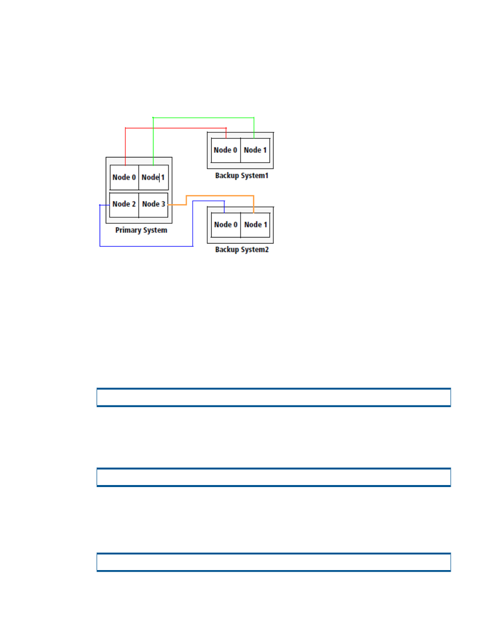
Setting Up Dedicated Node Pairs for RCFC
•
Verify that each Fibre Channel interface on each node on the primary Remote Copy system
connects to a dedicated Fibre Channel interface on each node on the backup Remote Copy
system.
RCFC requires a dedicated node pair per target. For example:
Figure 16 Remote Copy over Fibre Channel Dedicated Node Pairs
In
:
•
Fibre Channel interfaces on nodes 0 and 1 on the Primary System connect to Fibre Channel
interfaces on Backup System1 nodes 0 and 1, respectively.
•
Fibre Channel interfaces on nodes 2 and 3 on the Primary System connect to Fibre Channel
interfaces on Backup System2 nodes 0 and 1, respectively.
Setting Up the Remote Copy Interface for RCFC
Use the setup information you gathered in the
“RCFC Remote Copy Pair Worksheet” (page 32)
1.
Enter the following command for a Fibre Channel adaptor port on one storage system:
# controlport config rcfc -ct point -f
•
-ct point
- point-to-point mode
•
- Fibre Channel adaptor port to configure, expressed as node:slot:port
2.
To obtain the RCFC port positions, issue the showport -rcfc command:
# showport -rcfc
3.
Record the port positions in the
“RCFC Remote Copy Pair Worksheet” (page 32)
worksheet.
4.
Repeat
through
for each port on each system in the Remote Copy configuration.
5.
To verify that the Fibre Channel communication links have been established, issue the
showrctransport -rcfc
command.
# showrctransport -rcfc
The Fibre Channel adaptor ports should appear, and the State column should display new.
Setting Up Remote Copy over Fibre Channel
39