Electrical connections – KROHNE IFC 300 Converter EN User Manual
Page 89
ELECTRICAL CONNECTIONS
4
89
IFC 300
www.krohne.com
08/2010 - 4000069803 - MA IFC 300 R04 en
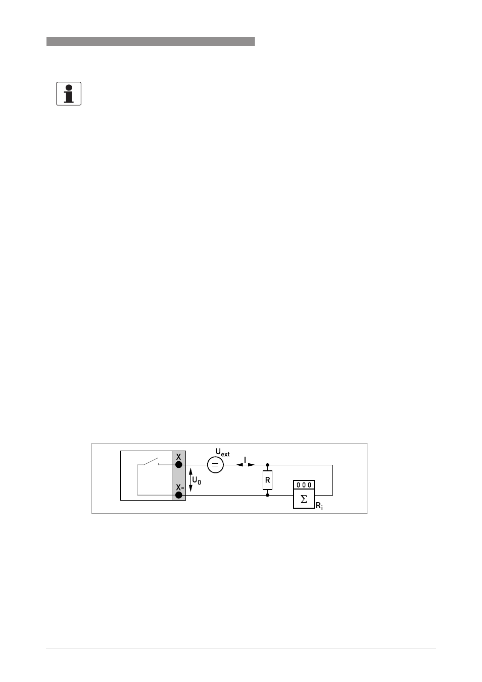
Pulse/frequency output passive, modular I/Os
• U
ext
≤ 32 VDC
• f
max
in the operating menu set to f
max
≤ 100 Hz:
I ≤ 100 mA
open:
I ≤ 0.05 mA at U
ext
= 32 VDC
closed:
U
0, max
= 0.2 V at I ≤ 10 mA
U
0, max
= 2 V at I ≤ 100 mA
• f
max
in the operating menu set to 100 Hz < f
max
≤ 10 kHz:
open:
I ≤ 0.05 mA at U
ext
= 32 VDC
closed:
U
0, max
= 1.5 V at I ≤ 1 mA
U
0, max
= 2.5 V at I ≤ 10 mA
U
0, max
= 5 V at I ≤ 20 mA
• If the following maximum load resistance R
L, max
is exceeded, the load resistance R
L
must be
reduced accordingly by parallel connection of R:
f ≤ 100 Hz: R
L, max
= 47 kΩ
f ≤ 1 kHz: R
L, max
= 10 kΩ
f ≤ 10 kHz: R
L, max
= 1 kΩ
• The minimum load resistance R
L, min
is calculated as follows:
R
L, min
= (U
ext
- U
0
) / I
max
• Can also be set as status output; refer to status output connection diagram.
• X designates the connection terminals A, B or D, depending on the version of the signal
converter.
INFORMATION!
For frequencies above 100 Hz, shielded cables are to be used in order to reduce effects from
electrical interferences (EMC).
Figure 4-52: Pulse frequency output passive P
p