Electrical connections, 12 connection diagrams of inputs and outputs – KROHNE IFC 300 Converter EN User Manual
Page 82
4
ELECTRICAL CONNECTIONS
82
IFC 300
www.krohne.com
08/2010 - 4000069803 - MA IFC 300 R04 en
4.12 Connection diagrams of inputs and outputs
4.12.1 Important notes
• All groups are electrically isolated from each other and from all other input and output
circuits.
• Passive operating mode: An external power supply is necessary to operate (activation) the
subsequent devices (U
ext
).
• Active operating mode: The signal converter supplies the power for operation (activation) of
the subsequent devices, observe max. operating data.
• Terminals that are not used should not have any conductive connection to other electrically
conductive parts.
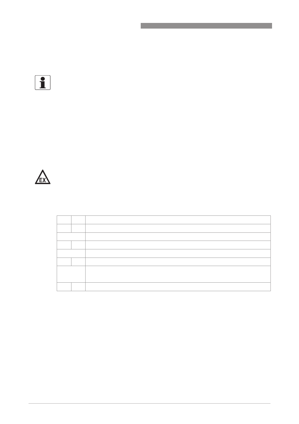
Description of used abbreviations
INFORMATION!
Depending on the version, the inputs/outputs must be connected passively or actively or acc. to
NAMUR EN 60947-5-6! Which I/O version and inputs/outputs are installed in your signal
converter are indicated on the sticker in the cover of the terminal compartment.
DANGER!
For devices used in hazardous areas, additional safety notes apply; please refer to the Ex
documentation.
I
a
I
p
Current output active or passive
P
a
P
p
Pulse/frequency output active or passive
P
N
Pulse/frequency output passive acc. to NAMUR EN 60947-5-6
S
a
S
p
Status output/limit switch active or passive
S
N
Status output/limit switch passive acc. to NAMUR EN 60947-5-6
C
a
C
p
Control input active or passive
C
N
Control input active acc. to NAMUR EN 60947-5-6:
Signal converter monitors cable breaks and short circuits acc. to EN 60947-5-6. Errors
indicated on LC display. Error messages possible via status output.
IIn
a
IIn
p
Current input active or passive