Operation – KROHNE IFC 300 Converter EN User Manual
Page 112
6
OPERATION
112
IFC 300
www.krohne.com
08/2010 - 4000069803 - MA IFC 300 R04 en
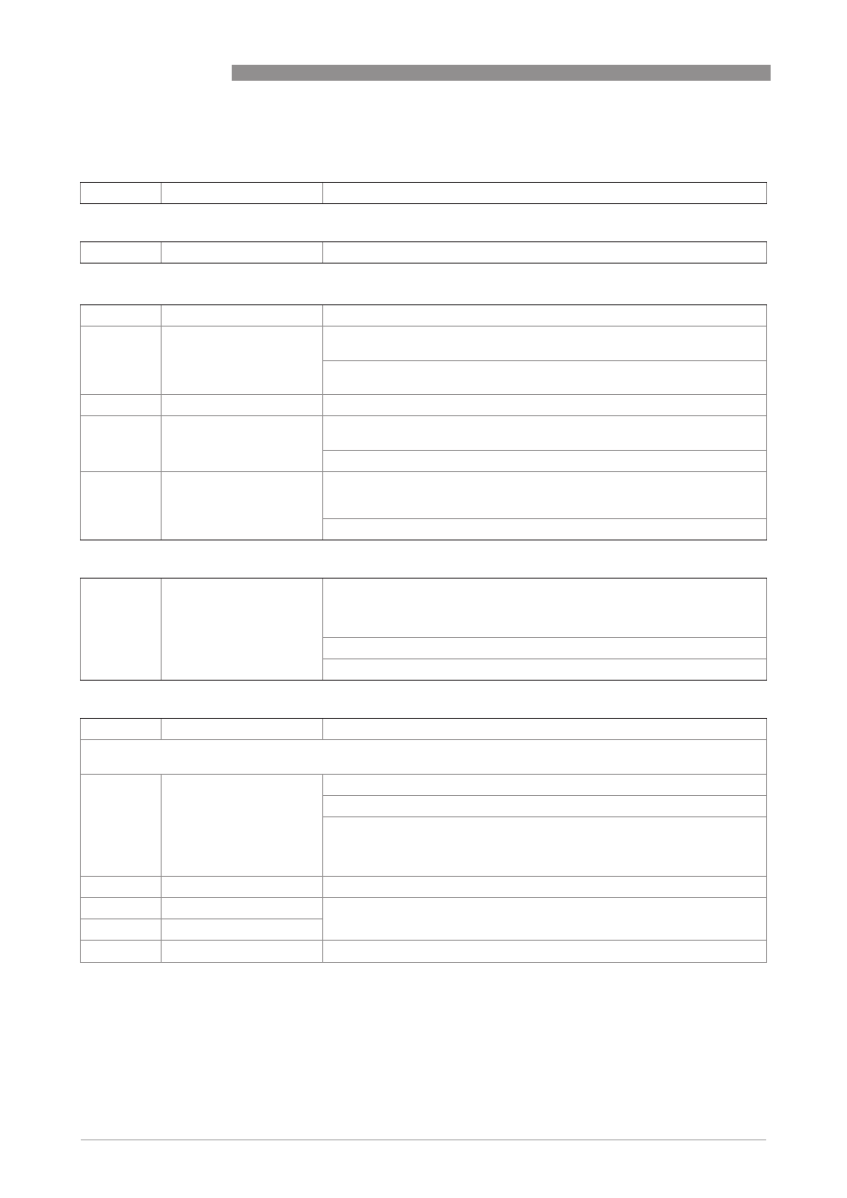
A4 station address (only for PROFIBUS)
A4
station address
Setting of device address.
A4 slave address (only for MODBUS)
A4
slave address
Setting of device address.
A5 digital outputs (only for HART
®
)
A5
digital outputs
Valid for all pulse outputs (terminals A, B and/or D) and counter 1.
A5.1
measurement
1) Select measurement: volume flow / mass flow (not valid for PF (partly
filled))
2) Use for all outputs? (also use this setting for Fct. A5.2...A5.4!)
Setting: no (only for pulse output D) / yes (for all digital outputs)
A5.2
pulse value unit
Selection of the unit from a list, depending on the measurement.
A5.3
value p. pulse
1) Setting for pulse output D (volume or mass value per pulse)
Setting: xxx.xxx in l/s or kg/s
2) Use for all outputs? Make setting, see Fct. A5.1 above!
A5.4
low flow cutoff
1) Setting for pulse output D (sets output value to "0")
(1st value = switching point / 2nd value = hysteresis),
condition: 2nd value ≤ 1st value
2) Use for all outputs? Make setting, see Fct. A5.1 above!
A6 GDC IR interface
A6
GDC IR interface
After this function has been activated an optical GDC adapter can be
connected to the LC display. If approximately 60 seconds pass without a
connection being established or after the adapter is removed, then the
function is exited and the optical keys are active once again.
Select: break (exit function without connection) /
activate (the IR interface (adapter) and interrupt the optical keys)
A7 process input
A7.1
device serial no.
Serial no. of the system.
The following process input parameters are only available, if the quick access has been activated in the menu "setup /
device / quick setup.
A7.2
zero calibration
Display of actual zero calibration value.
Query: calibrate zero?
Setting: break (return with ^) / standard (factory setting) /
manual (display last value, set new value, range: -1.00…+1 m/s) /
range: -1.00…+1 m/s) /
automatic (shows the current value as the new zero calibration value)
A7.3
size
Select from size table.
A7.4
GK
Depending on the selection in Fct. A7.4 / A7.5, the Fct. C1.1.0, 5 or 6 appears
Set value acc. to nameplate; range: 0.5…12 (20)
A7.5
GKL
A7.6
coil resistance Rsp
Field coil resistance at 20°C; range: 10.00...220 Ω