Operation – KROHNE IFC 300 Converter EN User Manual
Page 125
OPERATION
6
125
IFC 300
www.krohne.com
08/2010 - 4000069803 - MA IFC 300 R04 en
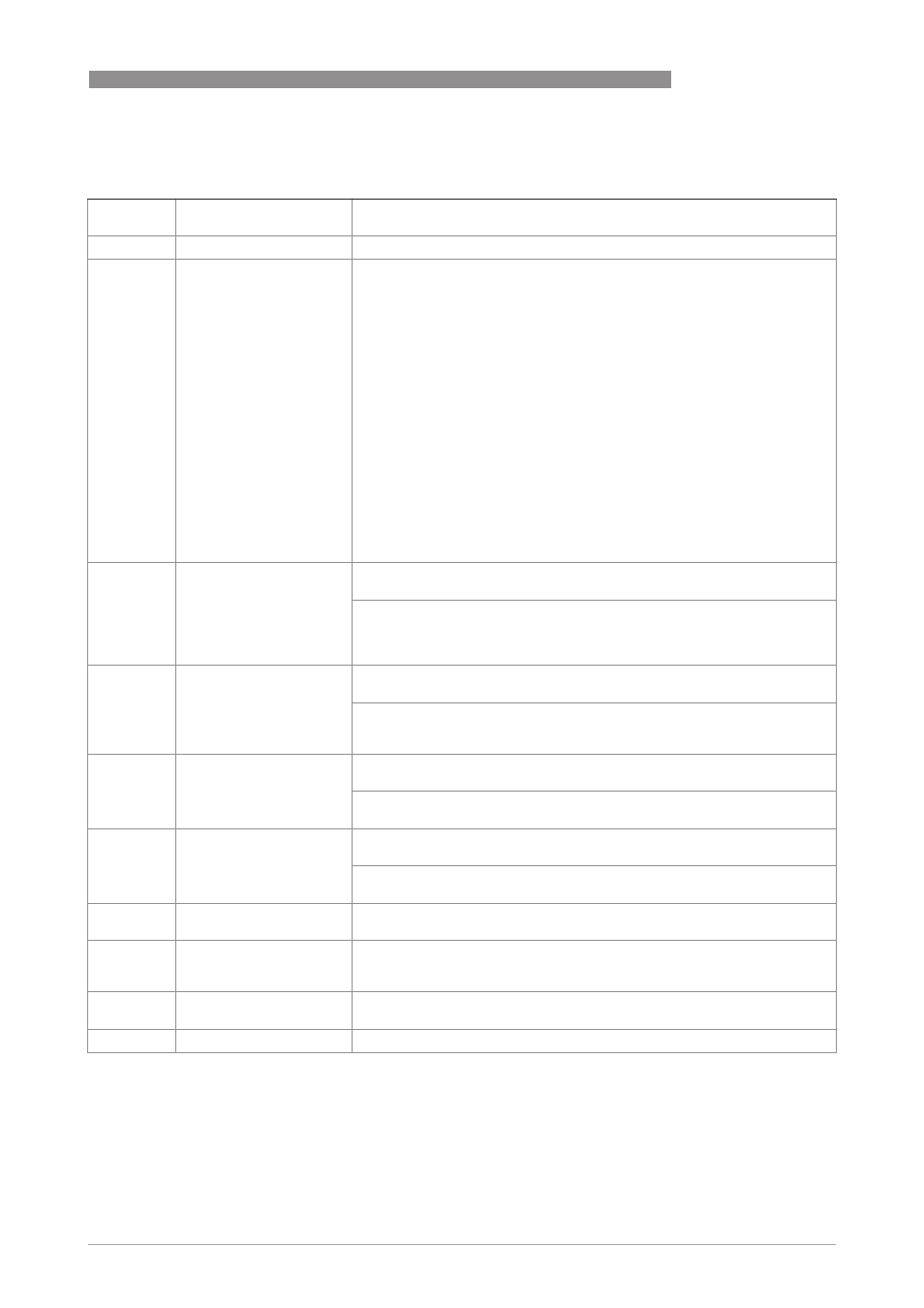
C2. status output X
C2.
status output X
X (Y) stands for one of the connection terminals A, B, C or D
stands for Fct. no. C2.2 (A) / C2.3 (B) / C2.4 (C) / C2.5 (D)
C2. .1
mode
The output shows the following measuring conditions:
out of specification (output activated, signals application error or error in
device refer to
Status messages and diagnostic information
on page 135 /
application error (output activated, signals application error or error in
device refer to
Status messages and diagnostic information
on page 135 /
polarity flow (polarity of the current flow) /
over range flow (over range of the flow) /
counter 1 preset (activates when counter X preset value is reached) /
counter 2 preset (activates when counter X preset value is reached) /
counter 3 preset (activates when counter X preset value is reached) /
output A (activated by the status of output Y, additional output data see
below) /
output B (activated by the status of output Y, additional output data see
below) /
output C (activated by the status of output Y, additional output data see
below) /
output D (activated by the status of output Y, additional output data see
below) /
off (switched off) /
empty pipe (when pipe empty, output activated) (contains the low-level
detection for PF option (partly filled)) /
error in device (when error, output activated)
C2. .2
current out Y
Only appears if output A...C is set under "mode (see above)", and this output
is a "current output".
Select:
polarity (is signalled) /
over range (is signalled) /
automatic range signals lower range
C2. .2
frequency out Y and pulse
output Y
Only appears if output A, B or D is set under "mode (see above)", and this
output is a "frequency/pulse output".
Select:
polarity (is signalled) /
over range (is signalled)
C2. .2
status output Y
Only appears if output A...D is set under "mode (see above)", and this output
is a "status output".
Same signal (like other connected status output, signal can be inverted, see
below)
C2. .2
limit switch Y and control
input Y
Only appears if output A...D / input A or B is set under "mode (see above)",
and this output / input is a "limit switch / control input".
Status off (is always selected here if status output X is connected with a limit
switch / control input Y.
C2. .2
off
Only appears if output A...D is set under "mode (see above)" and this output
is switched off.
C2. .3
invert signal
Select:
off (activated output supplies a high current, switch closed) /
on (activated output supplies a low current, switch open)
C2. .4
information
Serial no. of the I/O board, software version no. and production date of the
circuit board
C2. .5
simulation
Sequence see B1. status output X