Operation – KROHNE IFC 300 Converter EN User Manual
Page 126
6
OPERATION
126
IFC 300
www.krohne.com
08/2010 - 4000069803 - MA IFC 300 R04 en
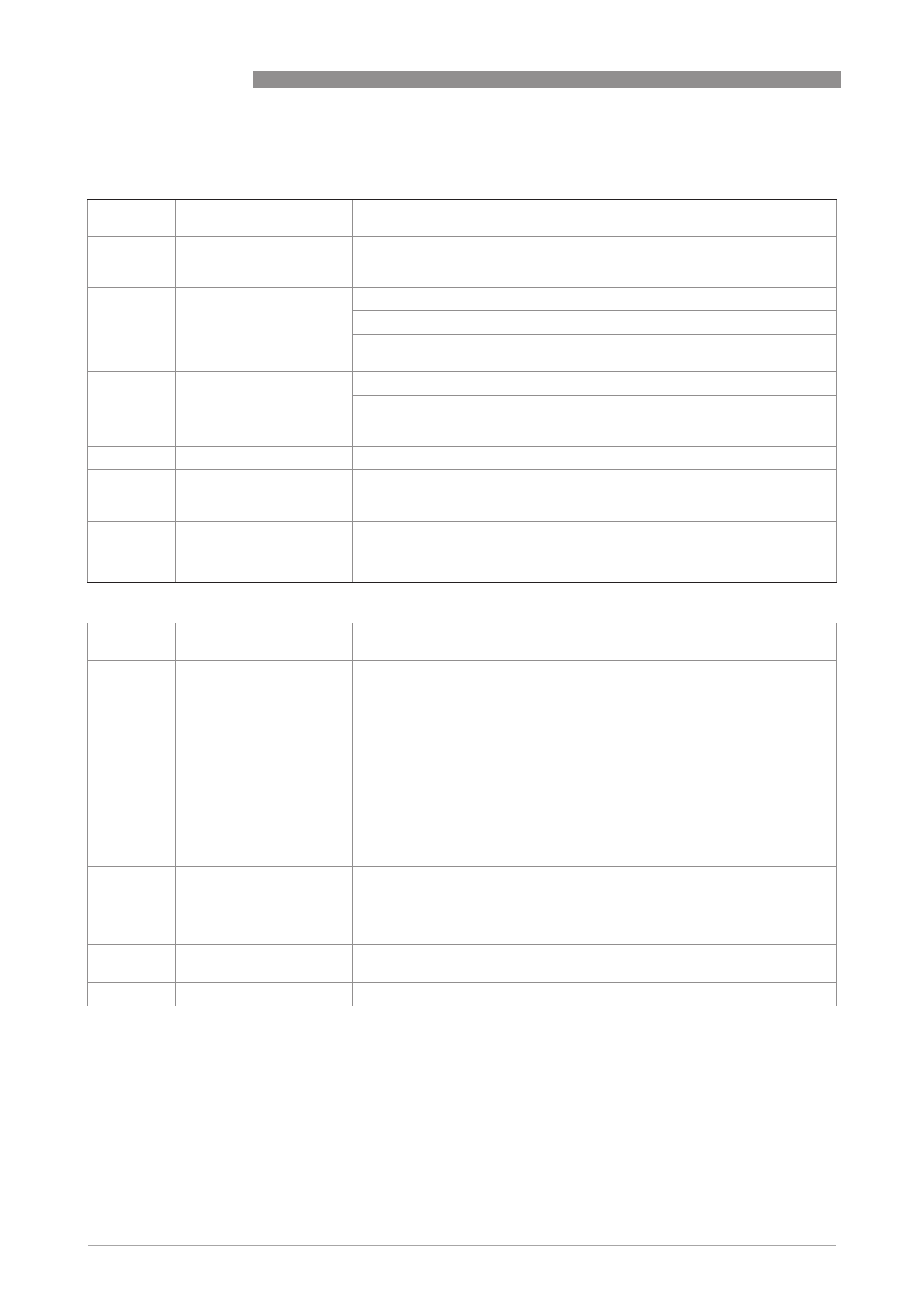
C2. limit switch X
C2.
limit switch X
X stands for one of the connection terminals A, B, C or D
stands for Fct. no. C2.2 (A) / C2.3 (B) / C2.4 (C) / C2.5 (D)
C2. .1
measurement
Select: volume flow / mass flow (not
not
not
not valid for PF (partly filled)) / diagnosis
value / flow speed / coil temperature / conductivity (not
not
not
not valid for PF (partly
filled)) and CAP (capacitive)) / level (only
only
only
only valid for PF (partly filled))
C2. .2
threshold
Switching level, set threshold with hysteresis
xxx.x ±x.xxx (format and unit depend on the measurement, see above)
(1st value = threshold / 2nd value = hysteresis),
condition: 2nd value ≤ 1st value
C2. .3
polarity
Set polarity, please note flow direction in C1.2.2!
Select: both polarities (plus and minus values are displayed) / positive
polarity (display for negative values = 0) / negative polarity (display for
positive values = 0) / absolute value (use for the output)
C2. .4
time constant
Range: 000.1…100 s
C2. .5
invert signal
Select:
off (activated output generates a high current, switch closed) /
on (activated output generates a low current, switch open)
C2. .6
information
Serial no. of the I/O board, software version no. and production date of the
circuit board
C2. .7
simulation
Sequence see B1. limit switch X
C2. control input X
C2.
control input X
X stands for connection terminal A or B
stands for Fct. no. C2.2 (A) / C2.3 (B)
C2. .1
mode
off (control input switched off) /
hold all outputs (hold current values, not display and counters) /
output Y (hold current values) /
all outputs to zero (current values = 0%, not display and counters) /
output Y to zero (current value = 0%) /
all counters (reset all counters to "0") /
counter "Z" reset (set counter 1, (2 or 3) to "0") /
stop all counters /
stop counter "Z" (stops counter 1, (2 or 3) /
zero outp.+stop Cnt. (all outputs 0%, stop all counters, not the display) /
external range Y (control input for external range of current output Y) - also
make this setting on current output Y (no check if current output Y is
available) /
error reset (all resettable errors are deleted)
C2. .2
invert signal
Select:
off (control input is activated when a current is applied at the input by voltage
to passive inputs or a low-value resistor to active inputs) /
on (control input is activated when no current is applied at the input, low
voltage to passive inputs or a high-value resistor to active inputs)
C2. .3
information
Serial no. of the I/O board, software version no. and production date of the
circuit board
C2. .4
simulation
Sequence see B 1. control input X