Operation – KROHNE IFC 300 Converter EN User Manual
Page 121
OPERATION
6
121
IFC 300
www.krohne.com
08/2010 - 4000069803 - MA IFC 300 R04 en
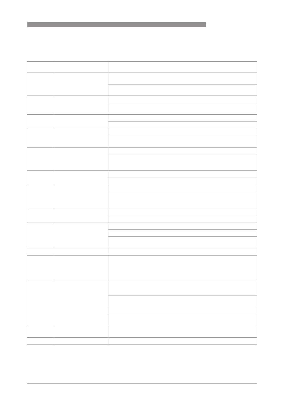
C2. current out X
C2.
current out X
X stands for one of the connection terminals A, B or C
stands for Fct. no. C2.2 (A) / C2.3 (B) / C2.4 (C)
C2. .1
range 0%…100%
Current range for the selected measurement, e.g. 4...20 mA,
corresponds to 0…100%
xx.x … xx.x mA; range: 0.00…20 mA
(condition: 0 mA ≤ 1st value ≤ 2nd value ≤ 20 mA)
C2. .2
extended range
Defines the min. and max. limits.
xx.x … xx.x mA; range: 03.5…21.5 mA
(condition: 0 mA ≤ 1st value ≤ 2nd value ≤ 21.5 mA)
C2. .3
error current
Specify error current.
xx.x mA; range: 3…22 mA (condition: outside of extended range)
C2. .4
error condition
The following error conditions can be selected.
Select: error in device (error category [F]) / application error (error category
[F]) / out of specification (error category [S])
C2. .5
measurement
Measurements for activating the output.
Select: volume flow / mass flow (not
not
not
not valid for PF (partly filled)) / diagnosis
value / flow speed / coil temperature / conductivity (not
not
not
not valid for PF (partly
filled)) and CAP (capacitive)) / level (only
only
only
only valid for PF (partly filled))
C2. .6
range
0…100% of the measurement set in Fct. C2. .5
0…xx.xx _ _ _ (format and unit depend on the measurement, see above)
C2. .7
polarity
Set polarity, please note flow direction in C1.2.2!
Select: both polarities (plus and minus values are displayed) / positive
polarity (display for negative values = 0) / negative polarity (display for
positive values = 0) / absolute value (use for the output)
C2. .8
limitation
Limitation before applying the time constant.
±
xxx … ±xxx%; range: -150…+150%
C2. .9
low flow cutoff
Sets output value to "0"
x.xxx ± x.xxx%; range: 0.0…20%
(1st value = switching point / 2nd value = hysteresis),
condition: 2nd value ≤ 1st value
C2. .10
time constant
Range: 000.1…100 s
C2. .11
special function
Select: off (switched off) /
automatic range (range is changed automatically, extended lower range,
only makes sense together with a status output) /
external range (change by control input, extended lower range, control input
must also be activated)
C2. .12
threshold
Appears only when Fct. C2. .11 threshold is activated between extended
and normal range. The automatic range function always changes from the
extended to the normal range when the 100% current is reached.
The upper 100% value of the hysteresis is then = 0. The threshold is then the
hysteresis value, instead of "threshold ± hysteresis" as shown in the display.
Range: 5.0…80%
(1st value = switching point / 2nd value = hysteresis),
condition: 2nd value ≤ 1st value
C2. .13
information
Serial no. of the I/O board, software version no. and production date of the
circuit board
C2. .14
simulation
Sequence see B1. current out X