Technical data, 6 dimensions and weights – KROHNE OPTIWAVE 5200 C_F EN User Manual
Page 116
8
TECHNICAL DATA
116
OPTIWAVE 5200 C/F
www.krohne.com
07/2013 - 4001904902 - HB OPTIWAVE 5200 R02 en
8.6 Dimensions and weights
Housing, process connection and antenna options
Housing, process connection and antenna options
Housing, process connection and antenna options
Housing, process connection and antenna options
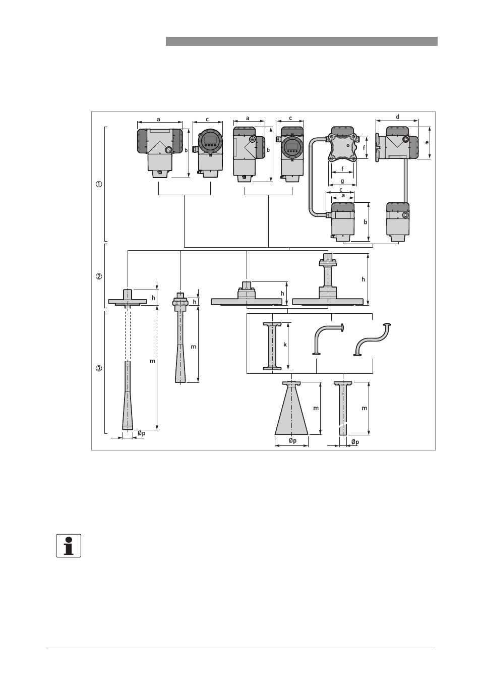
Figure 8-18: Housing, process connection and antenna options
1 Housing options.
Housing options.
Housing options.
Housing options. From left to right: compact converter with horizontal housing, compact converter with vertical hous-
ing, and remote converter (top) and antenna housing (bottom)
2 Process connection options.
Process connection options.
Process connection options.
Process connection options. From left to right: flange connection for PTFE Wave Horn antenna, threaded connection
for PP Wave Horn antenna, flange connection for Metallic Horn and Wave Guide antennas, flange connection with a
high-temperature (HT) extension for Metallic Horn and Wave Guide antennas
3 Antenna options.
Antenna options.
Antenna options.
Antenna options. From left to right: PTFE Wave Horn antenna, PP Wave Horn antenna, Metallic Horn antenna (with or
without an antenna extension option: straight, "L" or "S" extension), Wave Guide antenna
INFORMATION!
All housing covers have bayonet connectors unless it is an explosion-proof (XP / Ex d-approved)
device. The terminal compartment cover for explosion-proof devices has a thread with a flame
path.