Inputs, Calibration offset, Calibration – Watlow EZ-ZONE PM PID User Manual
Page 91
Watlow EZ-ZONE
®
PM PID Controller
•
88
•
Chapter 9 Features
Before Tuning
Before autotuning, the controller hardware must be installed correctly, and these basic configuration param-
eters must be set:
• Sensor Type [`SEn] (Setup Page, Analog Input Menu), and scaling, if required;
• Function [``Fn] (Setup Page, Output Menu) and scaling, if required.
How to Autotune a Loop
1. Enter the desired set point or one that is in the middle of the expected range of set points that you want
to tune for.
2. Enable TRU-TUNE+
®
.
3. Initiate an autotune. (See Autotuning in this chapter.)
When autotuning is complete, the PID parameters should provide good control. As long as the loop is in the
adaptive control mode, TRU-TUNE+
®
continuously tunes to provide the best possible PID control for the pro-
cess.
ç
WARNING! During autotuning, the controller sets the output to 100 percent and attempts to drive the process variable toward
the set point . Enter a set point and heat and cool power limits that are within the safe operating limits of your system .
Inputs
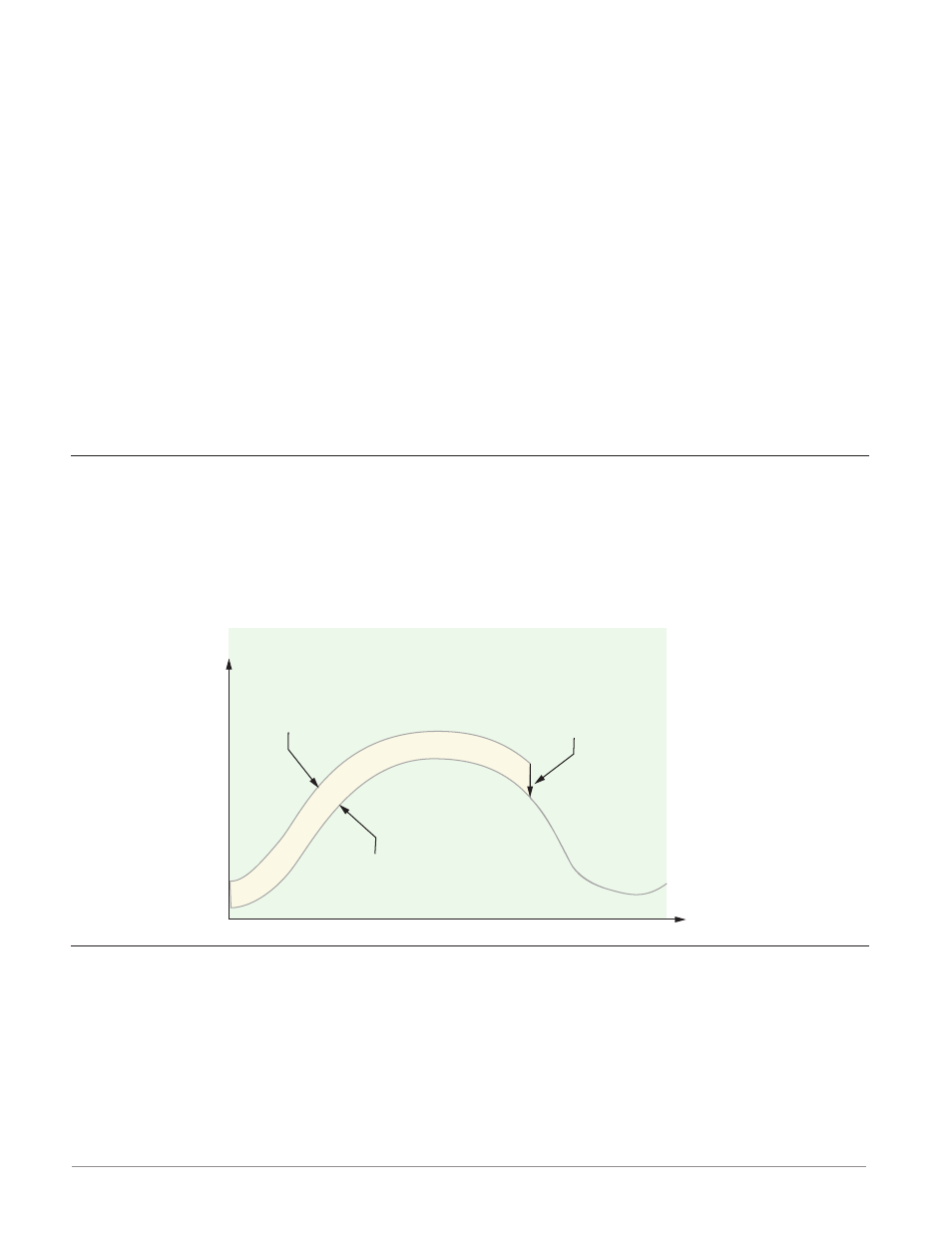
Calibration Offset
Calibration offset allows a device to compensate for an inaccurate sensor, lead resistance or other factors that
affect the input value. A positive offset increases the input value, and a negative offset decreases the input
value.
The input offset value can be viewed or changed with Calibration Offset [`i;CA] (Operations Page, Analog
Input Menu).
Calibration
Before performing any calibration procedure, verify that the displayed readings are not within published
specifications by inputting a known value from a precision source to the analog input. Next, subtract the dis-
played value with the known value and compare this difference to the published accuracy range specification
for that type of input.
Use of the Calibration Offset [`i;CA] parameter found in the Operations Page [oPEr] , Analog Input
Menu [``Ai] shifts the readings across the entire displayed range by the offset value. Use this parameter to
compensate for sensor error or sensor placement error. Typically this value is set to zero.
Equipment required while performing calibration: Obtain a precision source for millivolts, volts, milli-
amperes or resistance depending on the sensor type to be calibrated. Use copper wire only to connect the pre-
cision source to the controller’s input. Keep leads between the precision source and controller as short as pos-
Time
Temperature
Temperature Reading
from Sensor
Actual Process Temperature
Negative Calibration Offset will
compensate for the difference
between the Sensor Reading and
the Actual Temperature