Quencharc wiring example, Standard bus eia-485 communications, Modbus rtu or standard bus eia-485 communications – Watlow EZ-ZONE PM PID User Manual
Page 26: Wiring a serial eia-485 network
Watlow EZ-ZONE
®
PM PID Controller
•
23
•
Chapter 2 Install and Wire
Warning:
Óç
Use National Electric (NEC) or other
country-specific standard wiring and
safety practices when wiring and
connecting this controller to a power
source and to electrical sensors or
peripheral devices. Failure to do so
may result in damage to equipment
and property, and/or injury or loss
of life.
Note:
Maximum wire size termination and
torque rating:
• 0.0507 to 3.30 mm
2
(30 to 12
AWG) single-wire termination or
two 1.31 mm
2
(16 AWG)
• 0.8 Nm (7.0 lb.-in.) torque
Note:
Adjacent terminals may be labeled
differently, depending on the model
number.
Note:
To prevent damage to the control-
ler, do not connect wires to unused
terminals.
Note:
Maintain electrical isolation between
analog input 1, digital input-outputs,
switched dc/open collector outputs
and process outputs to prevent
ground loops.
Note:
The control output common termi-
nal and the digital common terminal
are referenced to different voltages
and must remain isolated.
Note:
This Equipment is suitable for use in
CLASS I, DIVISION 2, Groups A, B,
C and D or Non-Hazardous locations
only. Temperature Code T4A
Warning:
ç
Explosion Hazard - Dry contact clo-
sure Digital Inputs shall not be used
in Class I Division 2 Hazardous Loca-
tions unless switch used is approved
for this application.
Warning:
ç
Explosion Hazard – Substitution of
component may impair suitability
for CLASS I, DIVISION 2.
Warning:
ç
Explosion Hazard - Do not discon-
nect while the circuit is live or
unless the area is known to be free
of ignitable concentrations of flam-
mable substances.
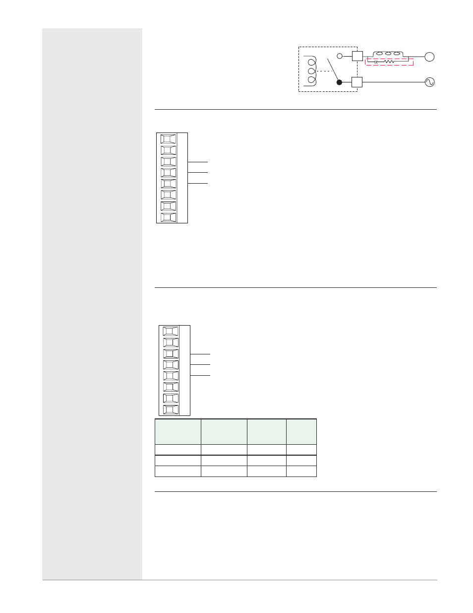
Quencharc Wiring Example
In this example the Quencharc circuit (Watlow
part# 0804-0147-0000) is used to protect PM
internal circuitry from the counter electro-
magnetic force from the inductive user load
when de-engergized. It is recommended that
this or an equivalent Quencharc be used when
connecting inductive loads to PM outputs.
Quencharc
User Load
N
L_
K_
Standard Bus EIA-485 Communications
Standard Bus
EIA-485
T-/R-
common
98
99
CF
CD
CE
B5
D6
D5
Slot C
T+/R+
• Wire T-/R- to the A terminal of
the EIA-485 port.
• Wire T+/R+ to the B terminal of
the EIA-485 port.
• Wire common to the common
terminal of the EIA-485 port.
• Do not route network wires
with power wires. Connect net-
work wires in daisy-chain fash-
ion when connecting multiple
devices in a network.
• Do not connect more than 16
EZ-ZONE PM controllers on a
network.
• maximum network length:
1,200 meters (4,000 feet)
• 1/8th unit load on EIA-485 bus
PM _ _ _ _ _-[A] AAAA _ _
Note:
A 120 Ω termination resistor
may be required across T+/R+
and T-/R-, placed on the last
controller on the network.
Note:
Do not leave a USB to EIA-485 converter connected to Standard Bus with-
out power (i.e., disconnecting the USB end from the computer while leaving
the converter connected on Standard Bus). Disturbance on the Standard
Bus may occur.
Modbus RTU or Standard Bus EIA-485 Communications
Modbus RTU or
Standard Bus EIA-485
T-/R-
common
98
99
CC
CA
CB
B5
D6
D5
Slot C
T+/R+
• Wire T-/R- to the A terminal of
the EIA-485 port.
• Wire T+/R+ to the B terminal of
the EIA-485 port.
• Wire common to the common
terminal of the EIA-485 port.
• Do not route network wires
with power wires. Connect net-
work wires in daisy-chain fash-
ion when connecting multiple
devices in a network.
• A termination resistor may be
required. Place a 120 Ω resistor
across T+/R+ and T-/R- of last
controller on network.
• Only one protocol per port is
available at a time: either Mod-
bus RTU or Standard Bus.
• Do not connect more than 16
EZ-ZONE PM controllers on a
Standard Bus network.
• Do not connect more than 247
EZ-ZONE PM controllers on a
Modbus RTU network.
• maximum network length:
1,200 meters (4,000 feet)
• 1/8th unit load on EIA-485 bus.
PM _ _ _ _ _-[1] AAAA _ _
Modbus-IDA
Terminal
EIA/TIA-485
Name
Watlow
Terminal
Label
Func-
tion
DO
A
CA or CD
T-/R-
D1
B
CB or CE
T+/R+
common
common
CC or CF
common
Wiring a Serial EIA-485 Network
Two example networks are shown below where the first one is using Wat-
low's Standard Bus and the other showing connections over Modbus. Do not
route network wires with power wires. Connect network wires in daisy-chain
fashion when connecting multiple devices in a network. A termination resis-
tor may be required. Place a 120 Ω resistor across T+/R+ and T-/R- of the last
controller on a network. Only one protocol per port is available at a time: ei-
ther Modbus RTU or Standard Bus.
Quencharc Note:
Switching pilot duty inductive loads
(relay coils, solenoids, etc.) with the me-
chanical relay, solid state relay or open
collector output options requires use of
an R.C. suppressor.
Note:
Do not leave a USB to EIA-485 con-
verter connected to Standard Bus
without power (i.e., disconnecting
the USB end from the computer
while leaving the converter connect-
ed on Standard Bus). Disturbance
on the Standard Bus may occur.