Digital output 5, 6, Switched dc wiring example using do 5 and 6 – Watlow EZ-ZONE PM PID User Manual
Page 22
Watlow EZ-ZONE
®
PM PID Controller
•
19
•
Chapter 2 Install and Wire
Warning:
Óç
Use National Electric (NEC) or other
country-specific standard wiring and
safety practices when wiring and
connecting this controller to a power
source and to electrical sensors or
peripheral devices. Failure to do so
may result in damage to equipment
and property, and/or injury or loss
of life.
Note:
Maximum wire size termination and
torque rating:
• 0.0507 to 3.30 mm
2
(30 to 12
AWG) single-wire termination or
two 1.31 mm
2
(16 AWG)
• 0.8 Nm (7.0 lb.-in.) torque
Note:
Adjacent terminals may be labeled
differently, depending on the model
number.
Note:
To prevent damage to the control-
ler, do not connect wires to unused
terminals.
Note:
Maintain electrical isolation between
analog input 1, digital input-outputs,
switched dc/open collector outputs
and process outputs to prevent
ground loops.
Note:
The control output common termi-
nal and the digital common terminal
are referenced to different voltages
and must remain isolated.
Note:
This Equipment is suitable for use in
CLASS I, DIVISION 2, Groups A, B,
C and D or Non-Hazardous locations
only. Temperature Code T4A
Warning:
ç
Explosion Hazard - Dry contact clo-
sure Digital Inputs shall not be used
in Class I Division 2 Hazardous Loca-
tions unless switch used is approved
for this application.
Warning:
ç
Explosion Hazard – Substitution of
component may impair suitability
for CLASS I, DIVISION 2.
Warning:
ç
Explosion Hazard - Do not discon-
nect while the circuit is live or
unless the area is known to be free
of ignitable concentrations of flam-
mable substances.
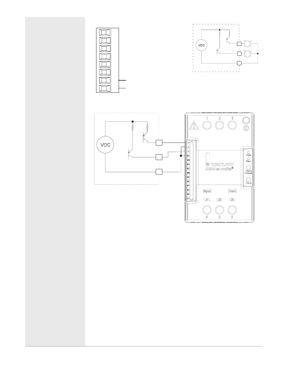
Digital Output 5, 6
98
99
CF
CD
CE
B5
D6
D5
Slot C
Digital Output
• Update rate 10 Hz
• Output voltage 24V
• Current limit, Output 5, 24
mA maximum
• Current limit, Output 6,
10 mA maximum driving
single pole DIN-A-MITE
• *Capable of driving a 3-pole
DIN-A-MITE
• Open-circuit voltage 22 to
32VÎ (dc)
PM _ _ [2,4] _ _-_ _ _ _ _ _ _
* Output 5 only
VDC
switched dc outputs
Internal Circuitry
B5
D6
D5
Switched DC Wiring Example Using DO 5 and 6
VDC
switched dc outputs
Internal Circuitry
+
+
-
-
DC80-60C0-0000
Htr 2
Htr 1
D5
D6
B5
Quencharc Note:
Switching pilot duty inductive loads
(relay coils, solenoids, etc.) with the
mechanical relay, solid state relay or
open collector output options requires
use of an R.C. suppressor.