Output 1 switched dc/open collector, Output 1 mechanical relay, form c, Output 1 universal process – Watlow EZ-ZONE PM PID User Manual
Page 23
Watlow EZ-ZONE
®
PM PID Controller
•
20
•
Chapter 2 Install and Wire
Warning:
Óç
Use National Electric (NEC) or other
country-specific standard wiring and
safety practices when wiring and
connecting this controller to a power
source and to electrical sensors or
peripheral devices. Failure to do so
may result in damage to equipment
and property, and/or injury or loss
of life.
Note:
Maximum wire size termination and
torque rating:
• 0.0507 to 3.30 mm
2
(30 to 12
AWG) single-wire termination or
two 1.31 mm
2
(16 AWG)
• 0.8 Nm (7.0 lb.-in.) torque
Note:
Adjacent terminals may be labeled
differently, depending on the model
number.
Note:
To prevent damage to the control-
ler, do not connect wires to unused
terminals.
Note:
Maintain electrical isolation between
analog input 1, digital input-outputs,
switched dc/open collector outputs
and process outputs to prevent
ground loops.
Note:
The control output common termi-
nal and the digital common terminal
are referenced to different voltages
and must remain isolated.
Note:
This Equipment is suitable for use in
CLASS I, DIVISION 2, Groups A, B,
C and D or Non-Hazardous locations
only. Temperature Code T4A
Warning:
ç
Explosion Hazard - Dry contact clo-
sure Digital Inputs shall not be used
in Class I Division 2 Hazardous Loca-
tions unless switch used is approved
for this application.
Warning:
ç
Explosion Hazard – Substitution of
component may impair suitability
for CLASS I, DIVISION 2.
Warning:
ç
Explosion Hazard - Do not discon-
nect while the circuit is live or
unless the area is known to be free
of ignitable concentrations of flam-
mable substances.
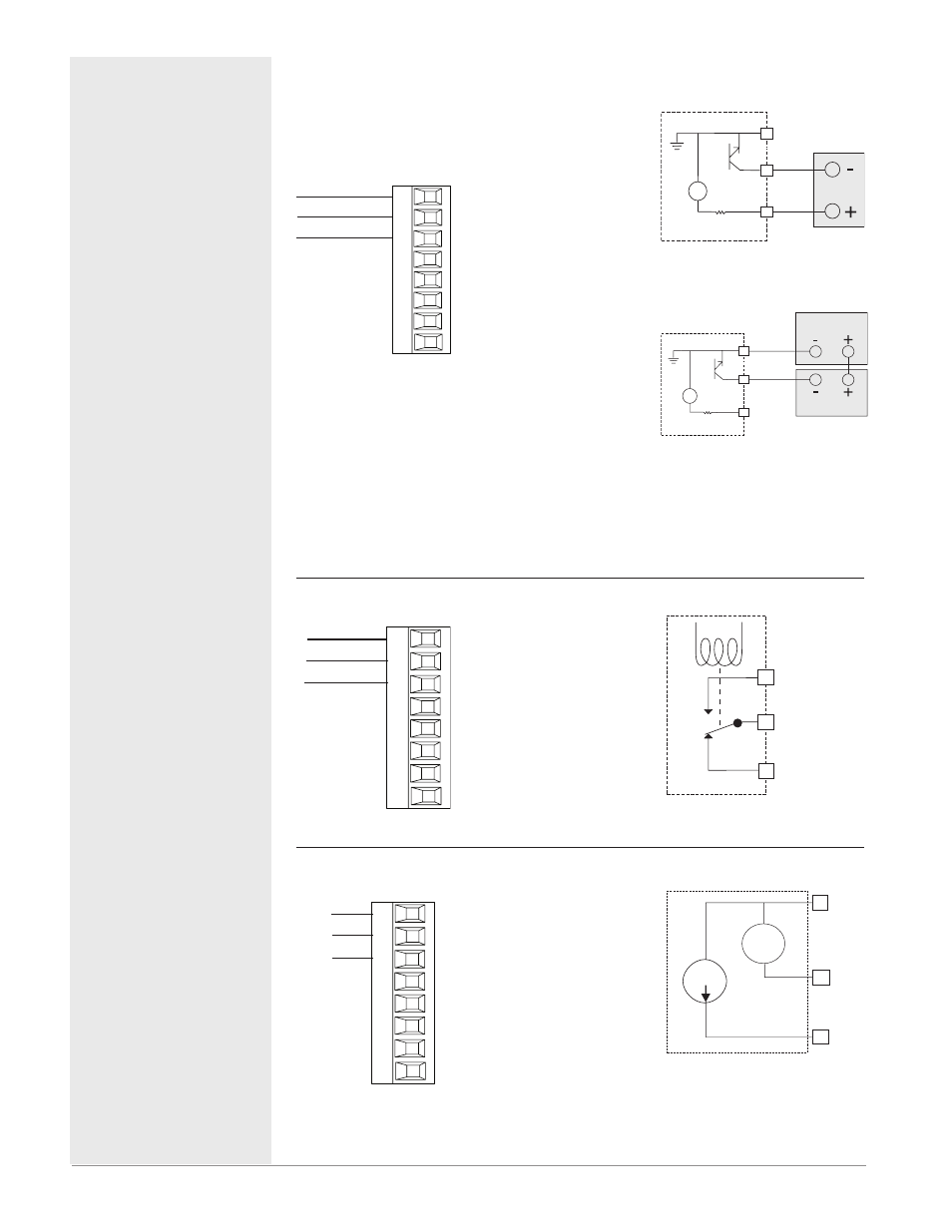
Output 1 Switched DC/Open Collector
dc - (open collector)
dc +
common
X1
W1
Y1
Slot A
Switched DC
• 30 mA dc maximum supply cur-
rent
• Short circuit limited to <50 mA
• 22 to 32VÎ (dc) open circuit
voltage
• Use dc- and dc+ to drive exter-
nal solid-state relay.
• DIN-A-MITE compatible
• Single-pole: up to 4 in parallel
or 4 in series
• 2-pole: up to 2 in parallel or 2 in
series
• 3-pole: up to 2 in series
Open Collector
• 100 mA maximum output cur-
rent sink
• 30VÎ (dc) maximum supply
voltage
• Any switched dc output can use
the common terminal.
• Use an external power supply to
control a dc load, with the load
positive to the positive of the
power supply, the load negative
to the open collector and com-
mon to the power supply nega-
tive.
See Quencharc note.
PM _ _ _ [C] _-_ AAAA _ _
Switched DC
dc +
dc -
common
24V
X1
Y1
W1
Open Collector
Load
Power Supply
dc -
common
24V
X1
W1
Y1
Output 1 Mechanical Relay, Form C
normally open
normally closed
common
L1
K1
J1
Slot A
• 5 A at 240VÅ (ac) or 30VÎ (dc)
maximum resistive load
• 20 mA at 24V minimum load
• 125 VA pilot duty at 120/240VÅ
(ac), 25 VA at 24VÅ (ac)
• 100,000 cycles at rated load
• Output does not supply power.
• for use with ac or dc
See Quencharc note.
PM _ _ _ [E] _-_ AAAA _ _
normally open
common
normally closed
L1
K1
J1
Output 1 Universal Process
Universal Process
(Output 1)
volts or current -
current +
volts +
F1
G1
H1
Slot A
• 0 to 20 mA into 800 Ω maxi-
mum load
• 0 to 10VÎ (dc) into 1 kΩ mini-
mum load
• scalable
• output supplies power
• cannot use voltage and current
outputs at same time
• Output may be used as re-
transmit or control.
PM _ _ _ [F] _-_ AAAA _ _
negative
volts +
current +
F1
G1
H1
4 to 20 mA
0 to 10 V
Quencharc Note:
Switching pilot duty inductive loads
(relay coils, solenoids, etc.) with the
mechanical relay, solid state relay or
open collector output options requires
use of an R.C. suppressor.