Output 2 no-arc relay, form a, Output 2 mechanical relay, form a, Output 2 solid-state relay, form a – Watlow EZ-ZONE PM PID User Manual
Page 25: L2 k2
Watlow EZ-ZONE
®
PM PID Controller
•
22
•
Chapter 2 Install and Wire
Warning:
Óç
Use National Electric (NEC) or other
country-specific standard wiring and
safety practices when wiring and
connecting this controller to a power
source and to electrical sensors or
peripheral devices. Failure to do so
may result in damage to equipment
and property, and/or injury or loss
of life.
Note:
Maximum wire size termination and
torque rating:
• 0.0507 to 3.30 mm
2
(30 to 12
AWG) single-wire termination or
two 1.31 mm
2
(16 AWG)
• 0.8 Nm (7.0 lb.-in.) torque
Note:
Adjacent terminals may be labeled
differently, depending on the model
number.
Note:
To prevent damage to the control-
ler, do not connect wires to unused
terminals.
Note:
Maintain electrical isolation between
analog input 1, digital input-outputs,
switched dc/open collector outputs
and process outputs to prevent
ground loops.
Note:
The control output common termi-
nal and the digital common terminal
are referenced to different voltages
and must remain isolated.
Note:
This Equipment is suitable for use in
CLASS I, DIVISION 2, Groups A, B,
C and D or Non-Hazardous locations
only. Temperature Code T4A
Warning:
ç
Explosion Hazard - Dry contact clo-
sure Digital Inputs shall not be used
in Class I Division 2 Hazardous Loca-
tions unless switch used is approved
for this application.
Warning:
ç
Explosion Hazard – Substitution of
component may impair suitability
for CLASS I, DIVISION 2.
Warning:
ç
Explosion Hazard - Do not discon-
nect while the circuit is live or
unless the area is known to be free
of ignitable concentrations of flam-
mable substances.
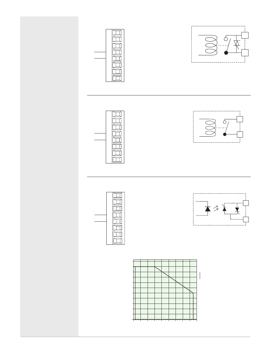
Output 2 NO-ARC Relay, Form A
common
normally open
L2
K2
Slot A
• 15 A at 85 to 264VÅ (ac) resis-
tive load only
• 2,000,000 cycle rating for NO-
ARC circuit
• 100 mA minimum load
• 2 mA maximum off state leakage
• Do not use on dc loads.
• Output does not supply power.
PM [4, 6, 8, 9] _ _ _ [H]-_ AAAA
_ _
L2
K2
Output 2 Mechanical Relay, Form A
common
normally open
L2
K2
Slot A
• 5 A at 240VÅ (ac) or 30VÎ (dc)
maximum resistive load
• 20 mA at 24V minimum load
• 125 VA pilot duty @ 120/240VÅ
(ac), 25 VA at 24VÅ (ac)
• 100,000 cycles at rated load
• Output does not supply power.
• for use with ac or dc
See Quencharc note.
PM _ _ _ _ [J]-_ AAAA _ _
L2
K2
Output 2 Solid-state Relay, Form A
Solid-state Relay
(Ouput 2)
common
normally open
L1
K1
J1
L2
K2
T1
S1
R1
Slot A
• 0.5 A at 20 to 264VÅ (ac) maxi-
mum resistive load
• 20 VA 120/240VÅ (ac) pilot duty
• opto-isolated, without contact
suppression
• maximum off state leakage of
105 microamperes
• Output does not supply power.
• Do not use on dc loads.
See Quencharc note.
PM _ _ _ _ [K]-_ AAAA _ _
L2
K2
1.1
0
-20
50
40
30
20
10
0
-10
60
70
Amps RMS
Ambient Temperature (
o
C)
0.1
1
0.2
0.9
0.3
0.4
0.5
0.6
0.7
0.8
1 Amp SSR Derating Curve
Sa
fe
Operating Area