Caution – Proface GP4600R - 12.1 Standard HMIs with Rear Mounting Options" User Manual
Page 166
166
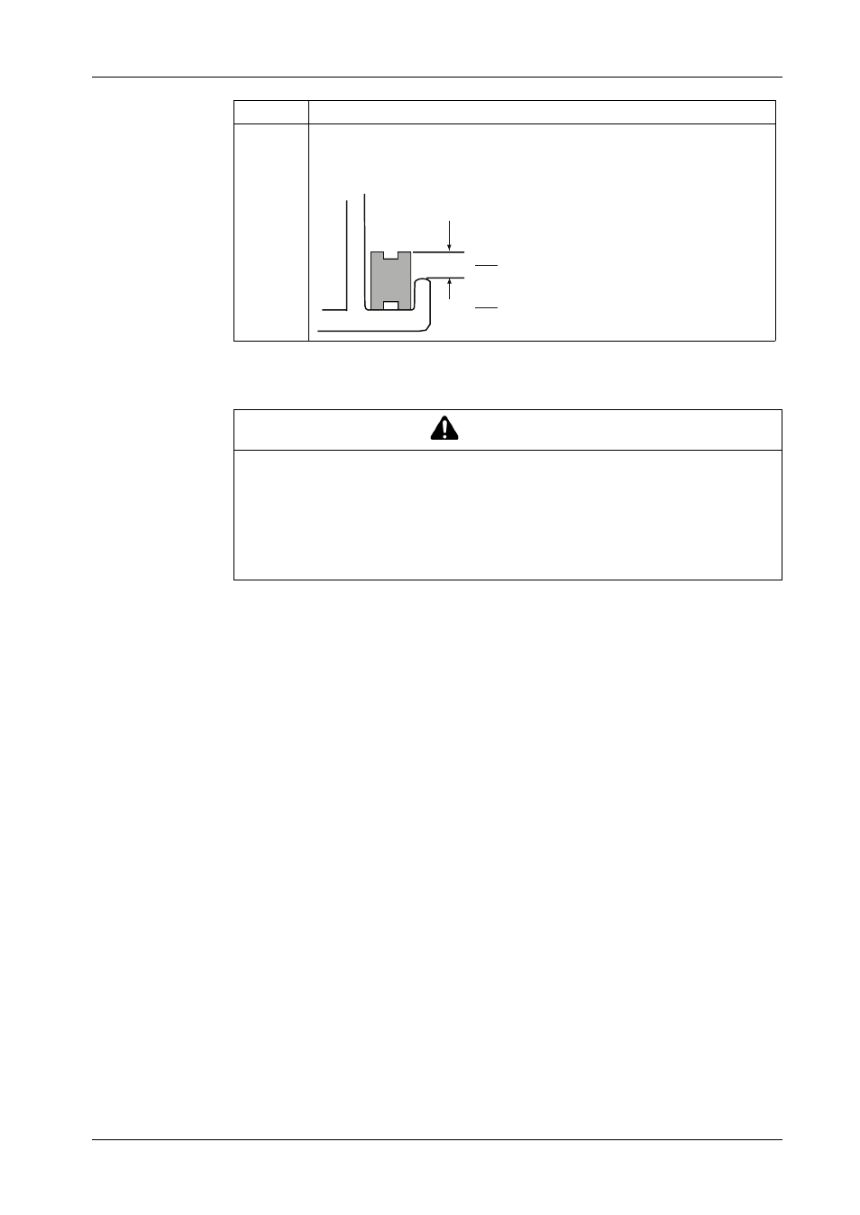
The gasket must be inserted correctly into the groove for IP65F moisture resistance
for the GP unit.
4
The upper surface of the gasket should protrude approximately 2.5 mm (0.1 in.)
from the groove. Check the gasket is inserted correctly before installing the GP
unit into a panel.
CAUTION
EQUIPMENT DAMAGE
z
Since the gasket is flexible but not elastic, be careful not to stretch it
unnecessarily.
z
Make sure the gasket seam is not inserted into any of the GP unit corners.
z
Insert the gasket in the installation groove
Failure to follow these instructions can result in injury or equipment damage.
Stage
Description
mm
in.
2.5
0.1
This manual is related to the following products:
- GP4500R - 10.4 Standard HMIs with Rear Mounting Options" GP4400R - 7.5 Standard HMI with Rear Mounting Options" GP4300R - 5.7 Standard HMI with Rear Mount" GP4300M - 5.7 Modular HMI" GP4200M - 3.5 Modular HMI" GP4500 - 10.4 W Model HMI" GP4400 - 7.0 W Model HMI" GP4300 - 5.7 W Model HMI" GP4200 - 3.5 W Model HMI" GP4600 - 12.1 Standard HMIs" GP4500 - 10.4 Standard HMIs" GP4400 - 7.5 Standard HMI" GP4300 - 5.7 Standard HMI" GP4200 - 3.5 Standard HMIs"