1 signal description, 2 vga connector, 3 vga dac filter – IEI Integration ICE-DB-T6 User Manual
Page 70: Figure 3-27: vga connector d-sub15, Table 3-20: vga signals description
Type 6 Carrier Board Design Guide
Page 60
3.11.1 Signal Description
Table 3-20 shows COM Express VGA signals, including pin number, signals, I/O, power
plane, terminal resistors, damping resistors and descriptions.
Pin
D-SUB15
Signal
I/O
Description
B89 1
VGA_RED
O Analog
Red component of analog DAC monitor
output, designed to drive a 37.5Ω equivalent
load.
B91 2
VGA_GRN
O Analog
Green component of analog DAC monitor
output, designed to drive a 37.5Ω equivalent
load.
B92 3
VGA_BLU
O Analog
Blue component of analog DAC monitor
output, designed to drive a 37.5Ω equivalent
load.
B93 13
VGA_HSYNC
O 3.3V
CMOS
Horizontal sync output to VGA monitor.
B94 14
VGA_VSYNC O 3.3V
CMOS
Vertical sync output to VGA monitor.
B95 15
VGA_I2C_CK
I/O 3.3V
CMOS
DDC clock line (I2C port dedicated to
identify VGA monitor capabilities). DDC data
line.
B96
VGA_I2C_DAT I/O 3.3V
CMOS
DDC clock line (I2C port dedicated to
identify VGA monitor capabilities). DDC data
line.
5-8,10
GND
Analog and Digital GND
9
DDC_POWER
5V DDC supply voltage for monitor
EEPROM
4,11
NC
Not
Connected
Table 3-20: VGA Signals Description
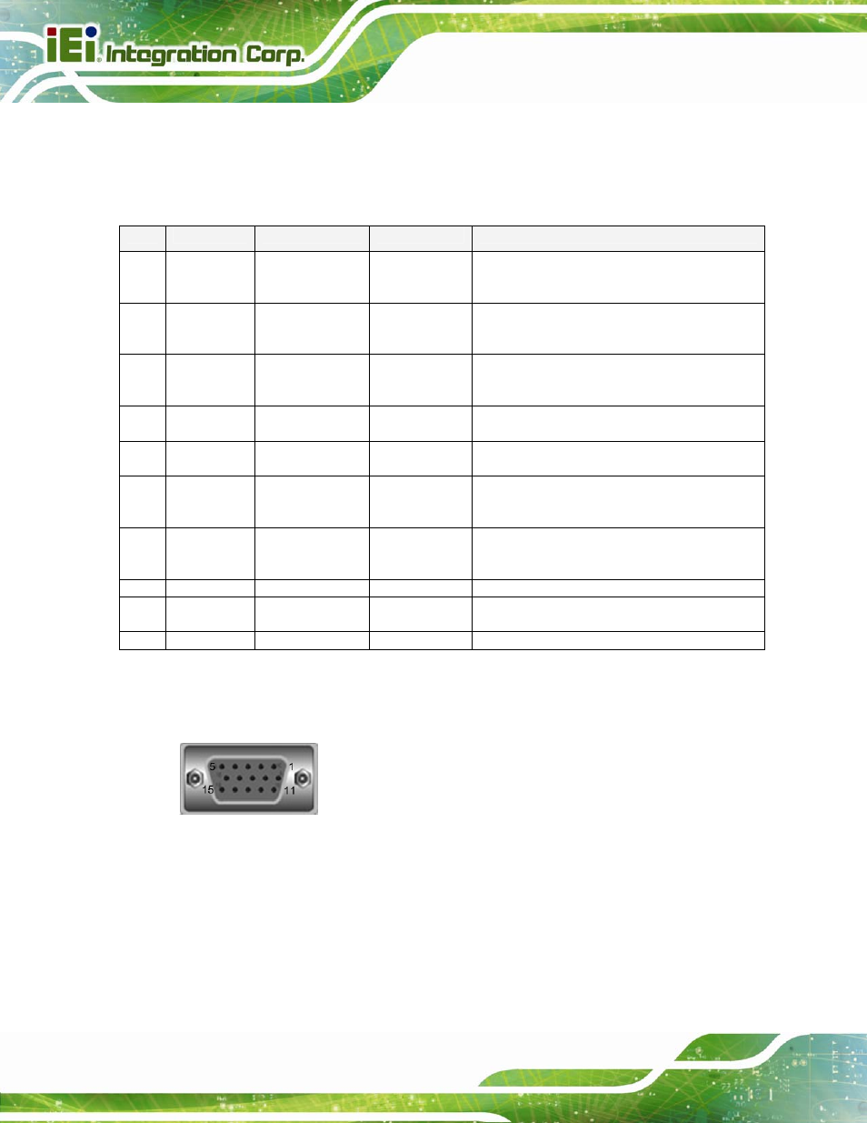
3.11.2 VGA Connector
Figure 3-27: VGA Connector D-SUB15
3.11.3 VGA DAC Filter
A video filter is required for each CRT DAC output. This video filter is to be placed in close
proximity to the VGA connector. The separation between each of the three video filters for
the RGB channels should be maximized if possible to minimize crosstalk.