2 implement, 7 audio codec interface (ac’97/hda), 1 signal description – IEI Integration ICE-DB-T6 User Manual
Page 61: Udio, Odec, Nterface, Ac’97/hda), Table 3-15: lvds impedance consideration
Type 6 Carrier Board Design Guide
Page 51
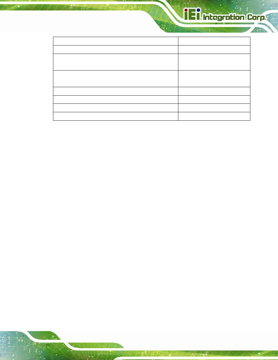
Single-ended Impedance
55 Ohms +/-15%
Spacing between pair to pairs (inter-pair) (s)
Min. 20mils
Spacing between differential pairs and high-speed periodic
signals
Min. 20mils
Spacing between differential pairs and low-speed non
periodic signals
Min. 20mils
Length matching between differential pairs (intra-pair)
+/- 20mils
Length matching between clock and data pairs (inter-pair)
+/- 20mils
Length matching between data pairs (inter-pair)
+/- 40mils
Spacing from edge of plane
+/- 40mils
Table 3-15: LVDS Impedance Consideration
3.6.4.2 Implement
Many carrier board designs do not need the full range of LVDS performance offered by
COM Express modules. It depends on the flat panel configuration of the COM Express
module, as well as the carrier board design, as to how many LVDS signal pairs are
supported. While the dual channel 24-bit LVDS configuration needs all ten LVDS signal
pairs, a single channel 18-bit LVDS configuration only requires four LVDS signal pairs. In
this case, all unused LVDS signal pairs should be left open on the carrier board. If the
LVDS display interface of the COM Express module is not implemented, all signals
associated with this interface should be left open.
3.7 Audio Codec Interface (AC’97/HDA)
All COM Express module types support Audio Codec '97 (AC'97) and/or High Definition
Audio (HDA) Digital Interface (AC-link) specifically designed for implementing audio and
modem I/O functionality. The corresponding signals can be found on the COM Express
module connector rows A and B.
3.7.1
Signal Description
Table 3-16 shows COM Express audio bus signal, including pin number, signals, I/O,
power plane, terminal resistors, damping resistors and descriptions.