2 pci express x1 slot, 3 pcie mini card, Figure 3-5: pci express x1 slot example – IEI Integration ICE-DB-T6 User Manual
Page 39
Type 6 Carrier Board Design Guide
Page 29
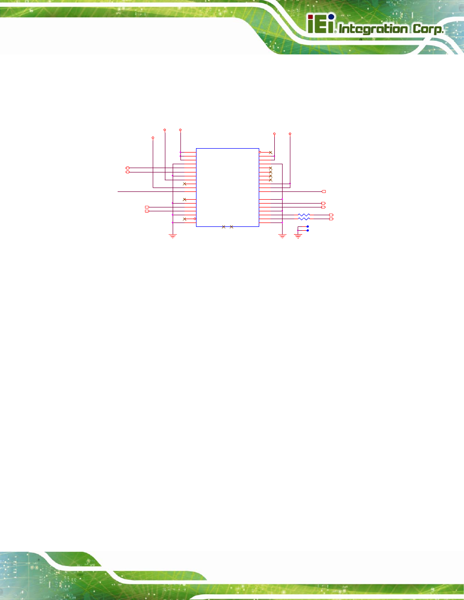
3.2.2 PCI Express x1 Slot
Table 3-3 illustrates the pinout definition for the standard PCI Express x1 connector. The
dashed lines in the diagram depict where each different connector type ends.
CB_RESET# 3,6,10,11,14,20
R125
0_4
1
2
+V12
+V3.3
+V3.3_DUAL
PCIE1
PCIE_X1
+12V03
B1
+12V04
B2
RSVD01
B3
GND05
B4
SMBCLK
B5
SMBDATA
B6
GND06
B7
3_3V03
B8
JTAG1
B9
3_3VAUX
B10
WAKE#
B11
PRSNT1#
A1
+12V01
A2
+12V02
A3
GND01
A4
JTAG2
A5
JTAG3
A6
JTAG4
A7
JTAG5
A8
3_3V01
A9
3_3V02
A10
PWRGD
A11
RSVD02
B12
GND07
B13
HSOP0
B14
HSON0
B15
GND08
B16
PRSNT2#
B17
GND09
B18
GND02
A12
REFCLK+
A13
REFCLK-
A14
GND03
A15
HSIP0
A16
HSIN0
A17
GND04
A18
NC1
NC1
NC2
NC2
PCIE_WAKE_UP#
+V3.3
+V12
PCIE_RX1-
3
PCIE_TX1-
3
PCIE_TX1+
3
PCIE_RX1+
3
CLK100M_PCIEx1_SLOT2- 4
CLK100M_PCIEx1_SLOT2+ 4
TP90
1
TP91
1
SMB_DAT
3,4,6,10,11,17,20
SMB_CK
3,4,6,10,11,17,20
R124
0_4
1
2
Figure 3-5: PCI Express x1 Slot Example
3.2.3 PCIe Mini Card
The PCI Express Mini Card add-in card is a small size form factor optimized for mobile
computing platforms equipped with communication applications such as Wireless LAN. A
small footprint connector can be implemented on the carrier board providing the ability to
install different PCI Express Mini cards. In addition to a PCI Express x1 link and a USB 2.0
link, the PCI Express Mini card interface utilizes the following control and reset signals,
which are provided by the COM Express module connector rows A and B.