2 ac coupling capacitors – IEI Integration ICE-DB-T6 User Manual
Page 35
Type 6 Carrier Board Design Guide
Page 25
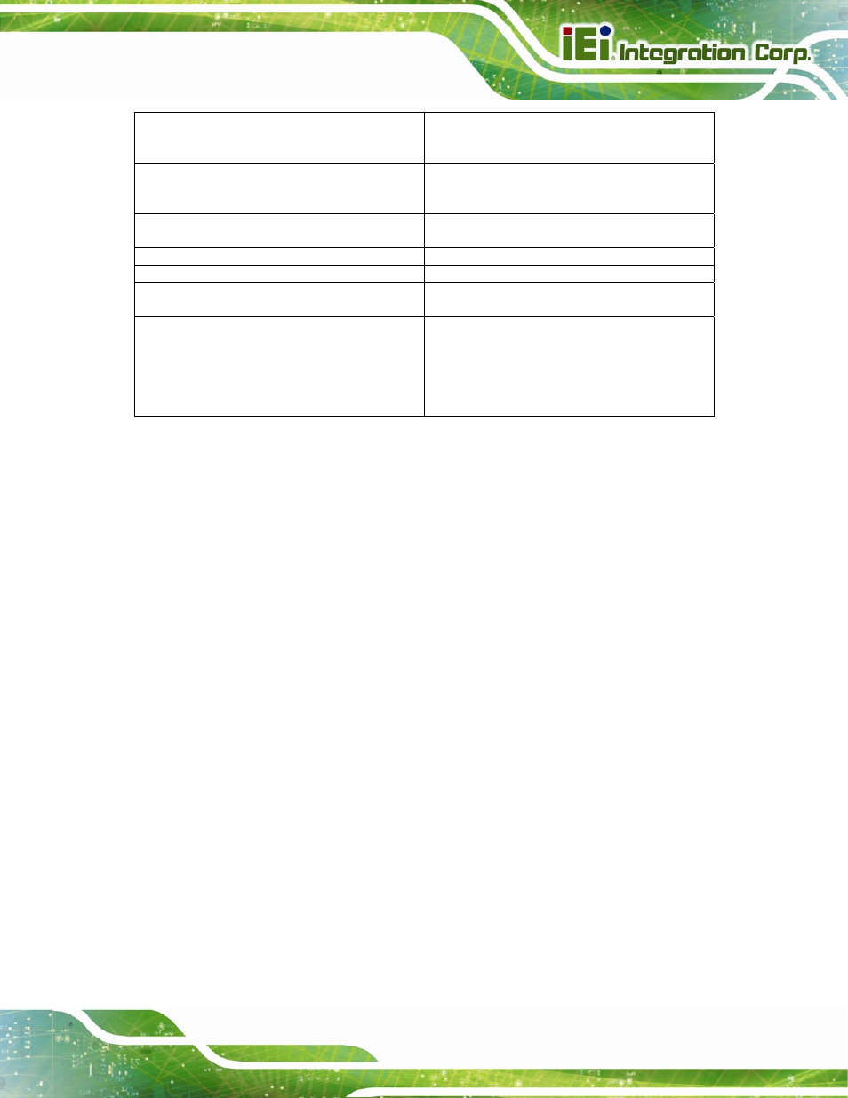
Length matching between RX and TX pairs
(inter-pair)
No strict electrical requirements. Keep
difference within a 3.0 inch delta to minimize
latency.
Length matching between reference clock
differential pairs REFCLK+ and REFCLK-
(intra-pair)
Max. 5mils
Length matching between reference clock
pairs (inter-pair)
No electrical requirements.
Reference plain
GND referenced preferred
Spacing from edge of plane
Min. 40mils
Via Usage
Max. 2 vias per TX trace Max. 4 vias per RX
trace
AC coupling capacitors
The AC coupling capacitors for the TX lines
are incorporated on the COM Express
module. The AC coupling capacitors for RX
signal lines have to be implemented on the
customer COM Express" carrier board.
Capacitor type: X7R
3.1.5.2 AC Coupling Capacitors
TX AC coupling capacitor is already embedded in the ICE modules. Users only need to
add the RX AC coupling capacitor on the carrier board. The PCI Express specification
requires that each lane of a PCI Express link be AC coupled between the driver and
receiver. The specification allows for the AC coupling capacitors to be located either on or
off the die. However, the AC coupling will be separated from the die and in the form of
discrete capacitors on the motherboard itself in most cases. The 0603 size capacitors are
acceptable, but the smaller size 0402 capacitors are strongly encouraged for reducing the
overall board area needed to place the capacitors.