8 reference circuit, 1 audio routing guideline, 1 analog power delivery – IEI Integration ICE-DB-T6 User Manual
Page 62: Eference, Ircuit, Figure 3-22: audio analog power example, Table 3-16: audio signals description, Type 6 carrier board design guide page 52
Type 6 Carrier Board Design Guide
Page 52
Pin
Signal
I/O
Description
A30 AC_RST#
O 3.3VSB CMOS
CODEC Reset.
A29 AC_SYNC
O 3.3V CMOS
48kHz fixed-rate, sample-synchronization signal to
the CODEC(s).
A32 AC_BITCLK
O 3.3V CMOS
12.228 MHz Serial Bit Clock for CODEC.
A33 AC_SDOUT
O 3.3V CMOS
Serial TDM data output to the CODEC.
B30
B29
B28
AC_SDIN0
AC_SDIN1
AC_SDIN2
I 3.3VSB CMOS
Serial TDM data inputs from up to 3 CODECs
Table 3-16: Audio Signals Description
3.8 Reference Circuit
Please refer to the schematic diagram of the baseboard. IEI ICE-DB-T6 reference carrier
board is embedded with the Realtek ALC892 audio controller. For the detailed
specifications of the Realtek ALC892, please go to
3.8.1 Audio Routing Guideline
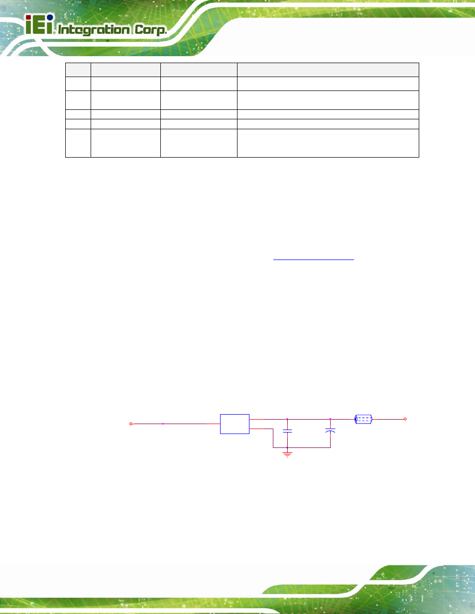
3.8.1.1 Analog Power Delivery
Clean analog power delivery to the audio codec and other audio components utilizing the
5-V analog supply is critical. Excessive system noise on this supply will degrade the entire
audio sub-system. Except the GND signal, users can use independent LDO to generate
clean audio analog power.
+V5_AUDIO
EC12
100U_SMD6_3_EC_25V
FB9
FB_80_6_600MA
1
2
C188
0.1U_4_Y_16V
Q9
GS78L05N_TO92_3
TO92_123
VOUT
1
VIN
3
GND
2
+V12
Figure 3-22: Audio Analog Power Example