1 ddi signal description: sdvo, 2 ddi signal description: displayport, Table 3-10: ddi pins and video interfaces mapping – IEI Integration ICE-DB-T6 User Manual
Page 56: Table 3-11: ddi signal descriptions - sdvo, Table 3-12: ddi signal descriptions - displayport
Type 6 Carrier Board Design Guide
Page 46
C38 DDI3_CTRLCLK
DP3_AUX+ HDMI3_CTRLCLK
D38 DDI3_CTRLDATA
DP3_AUX-
HDMI3_CTRLDATA
C36 DDI3_AUX+
C37 DDI3_AUX-
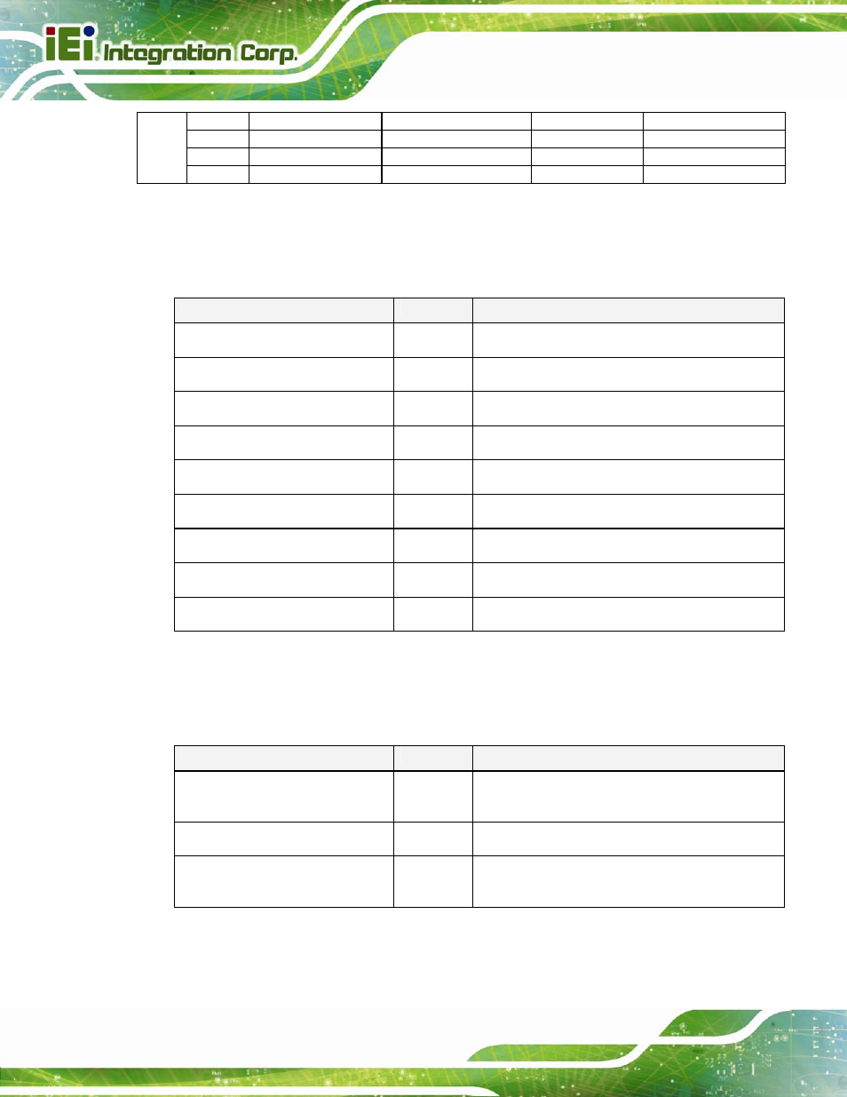
Table 3-10: DDI Pins and Video Interfaces Mapping
3.5.2.1 DDI Signal Description: SDVO
Signal
I/O
Description
SDVO1_RED+
SDVO1_RED-
O PCIe
Serial Digital Video red output differential pair.
SDVO1_GRN+
SDVO1_GRN-
O PCIe
Serial Digital Video green output differential pair.
SDVO1_BLU+
SDVO1_BLU-
O PCIe
Serial Digital Video blue output differential pair.
SDVO1_CK+
SDVO1_CK-
O PCIe
Serial Digital Video clock output differential pair.
SDVO1_INT+
SDVO1_INT-
I PCIe
Serial Digital Video interrupt input differential
pair.
SDVO1_TVCLKIN+
SDVO1_TVCLKIN-
I PCIe
Serial Digital Video TVOUT synchronization
clock input.
SDVO1_FLDSTALL+
SDVO1_FLDSTALL-
I PCIe
Serial Digital Video Field Stall input differential
pair.
SDVO1_CTRLCLK I/O
3.3V
CMOS
SDVO I2C clock line – set up SDVO peripherals
SDVO1_CTRLDATA I/O
3.3V
CMOS
SDVO I2C clock line – set up SDVO peripherals
Table 3-11: DDI Signal Descriptions - SDVO
3.5.2.2 DDI Signal Description: DisplayPort
Signal
I/O
Description
DP[1:3]_LANE[0:3]+
DP[1:3]_LANE0[0:3]-
O PCIe
Uni-directional main link for the transport of
isochronous streams and secondary-data
packets.
DP[1:3]_HPD I
3.3V
CMOS
Detection of Hot Plug / Unplug and notification of
the link layer.
DP[1:3]_AUX+
DP[1:3]_AUX-
I/O 3.3V
CMOS
Half-duplex bi-directional AUX channel for
services such as link configuration or
maintenance and EDID access.
Table 3-12: DDI Signal Descriptions - DisplayPort