3 lan link activity and speed led, 4 lan routing guideline, 1 impedance – IEI Integration ICE-DB-T6 User Manual
Page 65: Table 3-18: lan impedance consideration
Type 6 Carrier Board Design Guide
Page 55
3.9.3 LAN Link Activity and Speed LED
The COM Express module has four 3.3V open drain outputs to directly drive activity,
speed indication and link status LEDs. The 3.3V standby voltage should be used as LED
supply voltage so that the link activity can be viewed during system standby state. Since
LEDs are likely to be integrated into a RJ-45 connector with integrated magnetics module,
the LED traces need to be routed away from potential sources of EMI noise.
3.9.4 LAN Routing Guideline
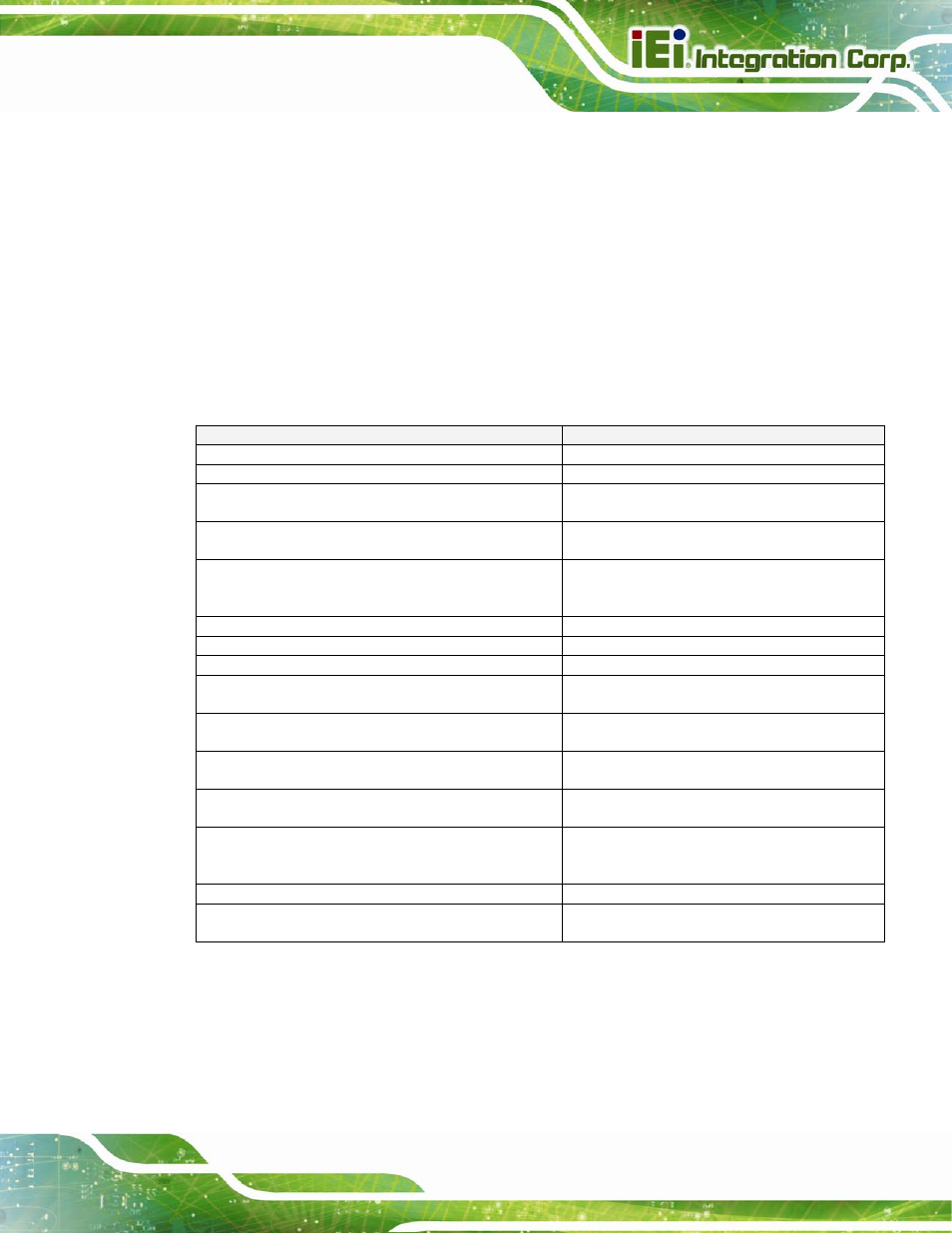
3.9.4.1 Impedance
Parameters
Routing
Transfer Rate
1.0 Gbits/sec
Maximum signal line length (coupled traces)
8.0 inches specified by COM Express "
Signal length used on COM Express module
(including the carrier board connector) "
3.0 inches specified by COM Express "
Signal length allowance for the COM Express
carrier board "
5.0 inches to the magnetics module
Maximum signal length between isolation
magnetics module and RJ-45 connector on the
carrier board
1.0 inch
Differential Impedance
95 Ohms +/-20%
Single-ended Impedance
55 Ohms +/-15%
Spacing between RX and TX pairs (inter-pair) (s)
Min. 50mils
Spacing between differential pairs and high-speed
periodic signals
Min. 300mils
Spacing between differential pairs and low-speed
non periodic signals
Min. 100mils
Length matching between differential pairs
(intra-pair)
Max. 5mils
Length matching between RX and TX pairs
(inter-pair)
Max. 30mils
Spacing between digital ground and analog ground
plane (between the magnetics module and RJ-45
connector)
Min. 60mils
Spacing from edge of plane
Min. 40mils
Via Usage
Max. of 2 vias on TX path Max. of 2 vias on
RX path
Table 3-18: LAN Impedance Consideration