48 9. motor/encoder cables – IAI America ISPDACR-ESD User Manual
Page 56
48
9. Motor/Encoder Cables
9.2
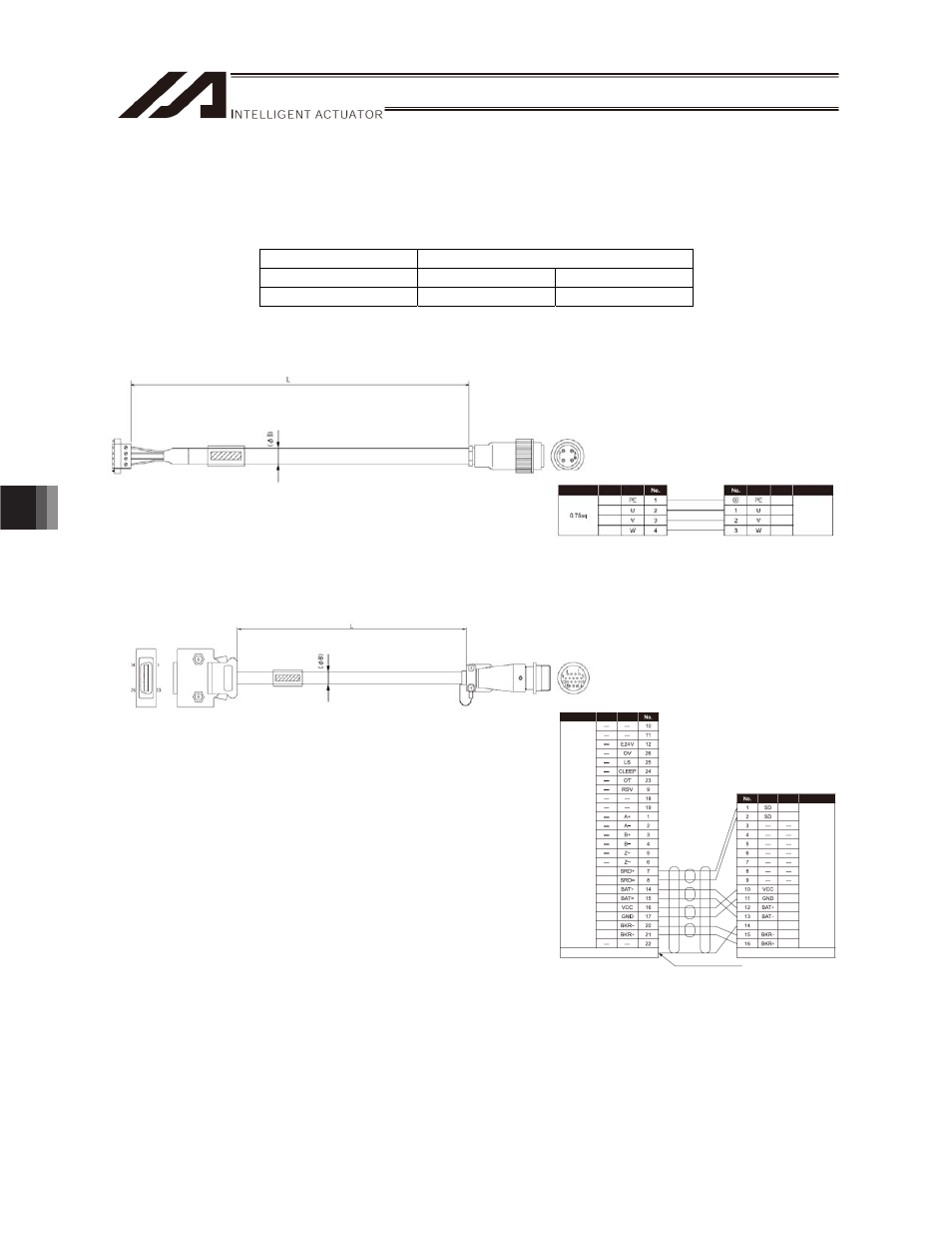
CE Specification (Option Indicated by “EU” in Model Number)
The same cables are used regardless of the actuator model. The applicable cables vary depending on
whether or not LSs are used.
Correspondence table of controllers and motor/encoder cables
Controller
XSEL-P/Q, SSEL, SCON
LS
Without LS
With LS
Applicable cables
[1], [2]
[1], [3]
[1] Motor
cable
CB-XEU-MA***
[2] Encoder
cable
CB-XEU1-PA***
Wiring
Color
Signal
Signal Color
Wiring
Orange
Green
Purple
Gray
Red
Black
Blue
Yellow
Orange
Green
Red
Black
Purple
Gray
Blue
Yellow
AWG26
(soldered)
The shield is clamped to the hood.
Drain wire and braided shield wires
AWG26
(soldered)
(As for wire color, “White/blue” indicates that
the band is white and insulator is blue.)
The shield is connected to the earth sleeve.
* *** indicates the cable length (L). Up to 30 m can be
specified.
Example) 080 = 8 m
[Minimum bending radius]
Movable: 48 mm
Fixed: 48 mm
* *** indicates the cable length (L). Up to 30 m can be
specified.
Example) 080 = 8 m
[Minimum bending radius]
Movable: 44 mm
Fixed: 29 mm
Wiring
Color
Signal
Signal
Color
Wiring
Green
Red
White
Black
Green
Red
White
Black
0.15 sq
(crimped)