Position of the dip switches – Burkert Type 8640 User Manual
Page 65
65
FELDBUSmoduleCANopen
13.2.3. IP54 terminating circuit
When installing a CANopen system, ensure that the terminating circuit of the data lines is correct. The circuit pre-
vents the occurrence of interference caused by signal reflection in the data lines. The trunk line must be terminated
at both ends with resistors of 120 Ω each and 1/4 W power loss.
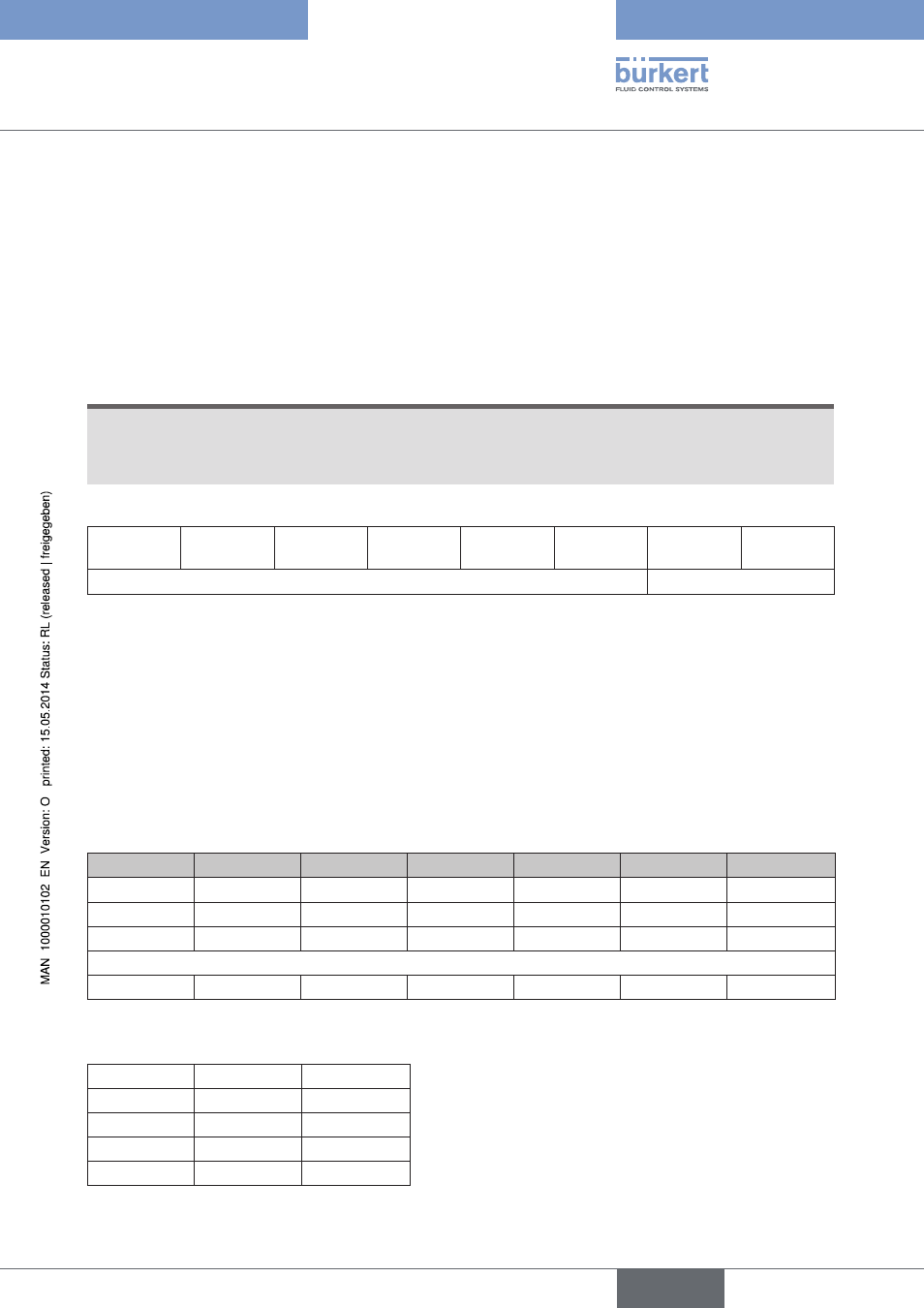
13.3. Position of the DIP switches
The DIP switches are used to make field bus module settings.
NOTE!
Changes made to the switch settings only take effect after the field bus module has been reset. Set the DIP
switch through the film using a screwdriver (the film is very durable).
'ON' setting = DIP switch to the right
1
(above)
2
3
4
5
6
7
8
(below)
Field bus module address
Baud rate
13.3.1. Field bus module address: DIP switches 1 to 6
The address of the field bus module can be set on DIP switches 1 ... 6 in the range 0 ... 63.
If an address between 63 and 127 is needed, this can be set via the object Index 3000 / Subindex 0. Then the
address is stored on an EEPROM (non-volatile) and is activated when:
• All DIP switches from 1 to 6 are set to 'ON' (address 63).
• A restart is carried out.
DIP 1
DIP 2
DIP 3
DIP 4
DIP 5
DIP 6
Address
ON
OFF
OFF
OFF
OFF
OFF
1
OFF
ON
OFF
OFF
OFF
OFF
2
ON
ON
OFF
OFF
OFF
OFF
3
...
ON
ON
ON
ON
ON
ON
63
The baud rate can be set on DIP switches 7 and 8:
DIP 7
DIP 8
Baud rate
OFF
OFF
20 kB
ON
OFF
125 kbaud
OFF
ON
250 kbaud
ON
ON
500 kbaud
english
Type 8640