Burkert Type 8640 User Manual
Page 30
30
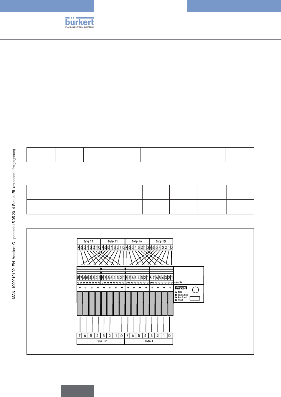
Example 3 - valve terminal with 16 valves (outputs) and 32 repeaters (inputs)
• PROFIBUS-DP address 6
• The valves 1-16 are assigned to outputs (PAA) bytes 11+12 in the process image.
• Repeaters 1, 3, 5, ... 15 are assigned to inputs (PAE) byte 10 in the process image.
• Repeaters 2, 4, 6, ... 16 are assigned to inputs (PAE) byte 16 in the process image.
• Repeaters 1, 17, 19, ... 31 are assigned to inputs (PAE) byte 11 in the process image.
• Repeaters 1, 18, 20, ... 32 are assigned to inputs (PAE) byte 17 in the process image.
• Mode: Shifted inputs
• Input filter active
DIP Switches
1
2
3
4
5
6
7
8
OFF
ON
ON
OFF
OFF
OFF
OFF
OFF
User parameter byte 11 User_Prm_Data 64 hex
Configuration:
Byte No. (slot)
1 (0)
2 (1)
3 (2)
4 (3)
5 (4)
Identification in Hex (Dec)
10 (016)
10 (016)
10 (016)
10 (016)
21 (032)
Process image output (PAA)
11-12
Process image input (PAE)
10
16
11
17
Allocation of inputs and outputs to control process image
Process image
Process image
Inputs (PAE)
Outputs (PPA)
Valve
Valve
Valve
Valve
Valve
Valve
Valve
Valve
Valve
Valve
Valve
Valve
Valve
Valve
Valve
Valve
Figure 16:
Allocation of inputs and outputs to control process image
Configurationandparameter
settingsforPROFIBUSDP
english
Type 8640