Canopen, ip54 - overview – Burkert Type 8640 User Manual
Page 63
63
FELDBUSmoduleCANopen
13.1.2. IP20 field bus connection
For connecting the field bus a 9-pole D-SUB connection is used with the following pin assignment (plug in
device, socket on cable).
Pin No.
Signal name
Pin No.
Signal name
1
not used
6
not used
2
CAN LOW
7
CAN HIGH
3
GND
8
not used
4
not used
9
not used
5
not used
13.1.3. IP20 terminating circuit
When installing a CANopen system, ensure that the terminating circuit of the data lines is correct. The circuit pre-
vents the occurrence of interference caused by signal reflection in the data lines. The trunk line must be terminated
at both ends with resistors of 120 Ω each and 1/4 W power loss.
For the IP20 variant a terminal resistance of 120 Ohm between the two bus connections CAN High and
CAN Low can be added using a bridge in the 9-pole D-SUB field bus connection between pin 4 and pin 8.
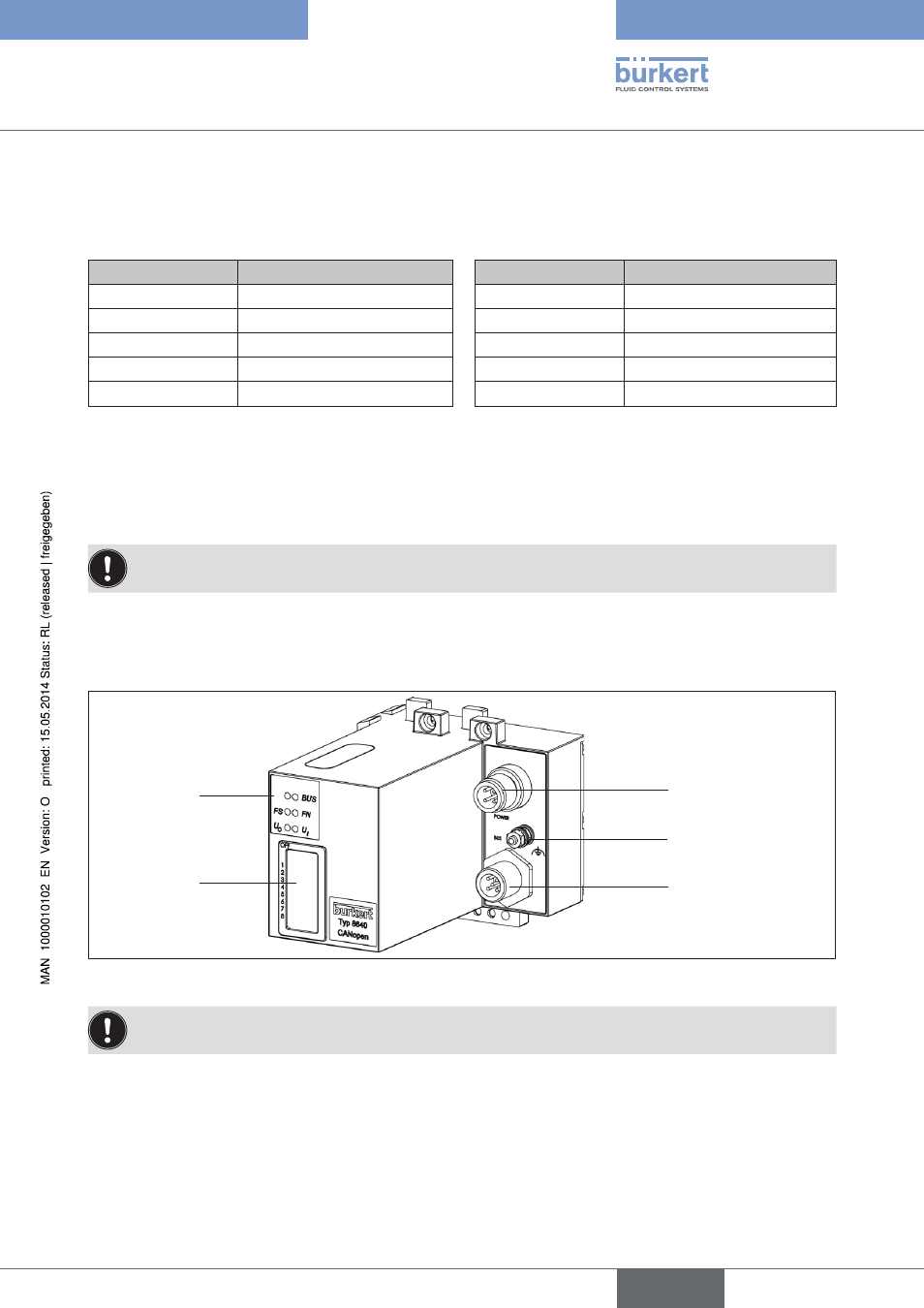
13.2. CANopen, IP54 - overview
LED Status
Display
DIP Switches
Power Supply
Functional earth
Field bus connection
Figure 42:
Overview field bus module CANopen IP54
The DIP switches can be operated through the covering film.
english
Type 8640