Installation on standard rail, Installation of airline quick – Burkert Type 8640 User Manual
Page 113
113
InstallationofAirLINEQuick
23.2. Installation on standard rail
DANGER!
Risk of electric shock!
• Before reaching into the device or the equipment, switch off the power supply and secure to prevent
reactivation!
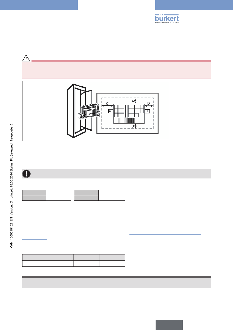
Figure 81:
Installation of a valve block into a control cabinet
→
Fasten the standard rail firmly in the control cabinet.
→
Establish a short, wide PE connection between the standard rail and the control cabinet.
The valve terminal must be freely accessible from above. Ensure good heat dissipation!
Recommended distance when installing in a control cabinet:
A
30 mm
C
30 mm
B
30 mm
D
60 mm
23.3. Installation of AirLINE Quick
To install AirLINE Quick, a notch must be first of all provided on the base or the wall of the control cabinet, e.g.
through lasing or punching.
For the dimensions of the relevant flange image, refer to chapter “23.4. Dimensions of the flange images for
AirLINE Quick”
.
The distances to the left, right, front and top depend on the selected valve terminal configuration.
Recommended distance in the control cabinet to the valve terminal:
left
right
front
top
30 mm
60 mm
30 mm
50 mm
NOTE!
The opening on the control cabinet must be burr-free to prevent damage to the seal of the AirLINE
Quick adapter.
→
Without damaging the seal of the AirLINE Quick adapter, insert it into the groove of the flange opening.
english
Type 8640