Power supply ip54, Ip54 field bus connection – Burkert Type 8640 User Manual
Page 64
64
FELDBUSmoduleCANopen
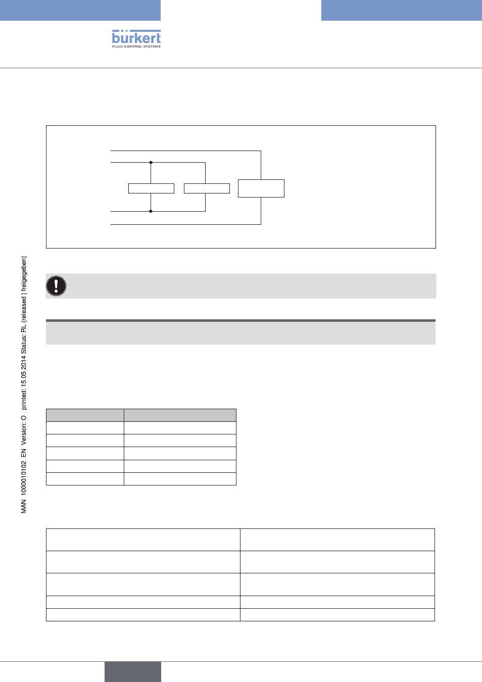
13.2.1. Power supply IP54
The 4-pole circular plug-in connector for the power supply is configured as follows:
Electronics
Inputs
Valves /
Outputs
24 V DC (1)
valves /
outputs
24 V DC (2)
logic
GND (3)
logic
GND (4)
valves /
outputs
Pin 1: +24 V - valves (outputs)
Pin 2: +24 V - logic + inputs
Pin 3: GND - logic + inputs
Pin 4: GND - valves (outputs)
Figure 43:
Power supply configuration
Pin 1 of the power supply must be supplied with a 4 A medium time-lag fuse; Pin 2 with 1 A.
NOTE!
To ensure electromagnetic compatibility (EMC) connect the screw terminal FE (functional earth) to earth
potential using a short cable (30 cm).
13.2.2. IP54 field bus connection
For the field bus connection the 5-pole M12 Micro-Style plug-in connector (plug) as specified by CANopen is used
with the following pin assignment.
Pin No.
Signal name
1
Drain (shielding)
2
not used
3
GND
4
CAN HIGH
5
CAN LOW
The bus drivers are supplied internally via a voltage source which is galvanically isolated from the supply voltage.
For this reason it is not necessary for separate voltage to be supplied from the bus via pin 2 and pin 3.
Accessories
CANopen, configurable M12 plug-in connector,
5-pole, straight coupling
Id.-No. 917 116
CANopen, configurable M12 plug-in connector,
5-pole, straight plug
Id.-No. 902 627
Power supply, configurable M12 plug-in connector,
4-pole, straight coupling
Id.-No. 902 552
Terminal resistance, M12 plug, 5-pole
Id.-No. 902 628
Y-piece, M12, 5-pole
Id.-No. 778 643
english
Type 8640