Profibus dp/v1, ip54 - overview, Power supply ip54 – Burkert Type 8640 User Manual
Page 20
20
FieldbusmodulePROFIBUSDP/V1
8.2.
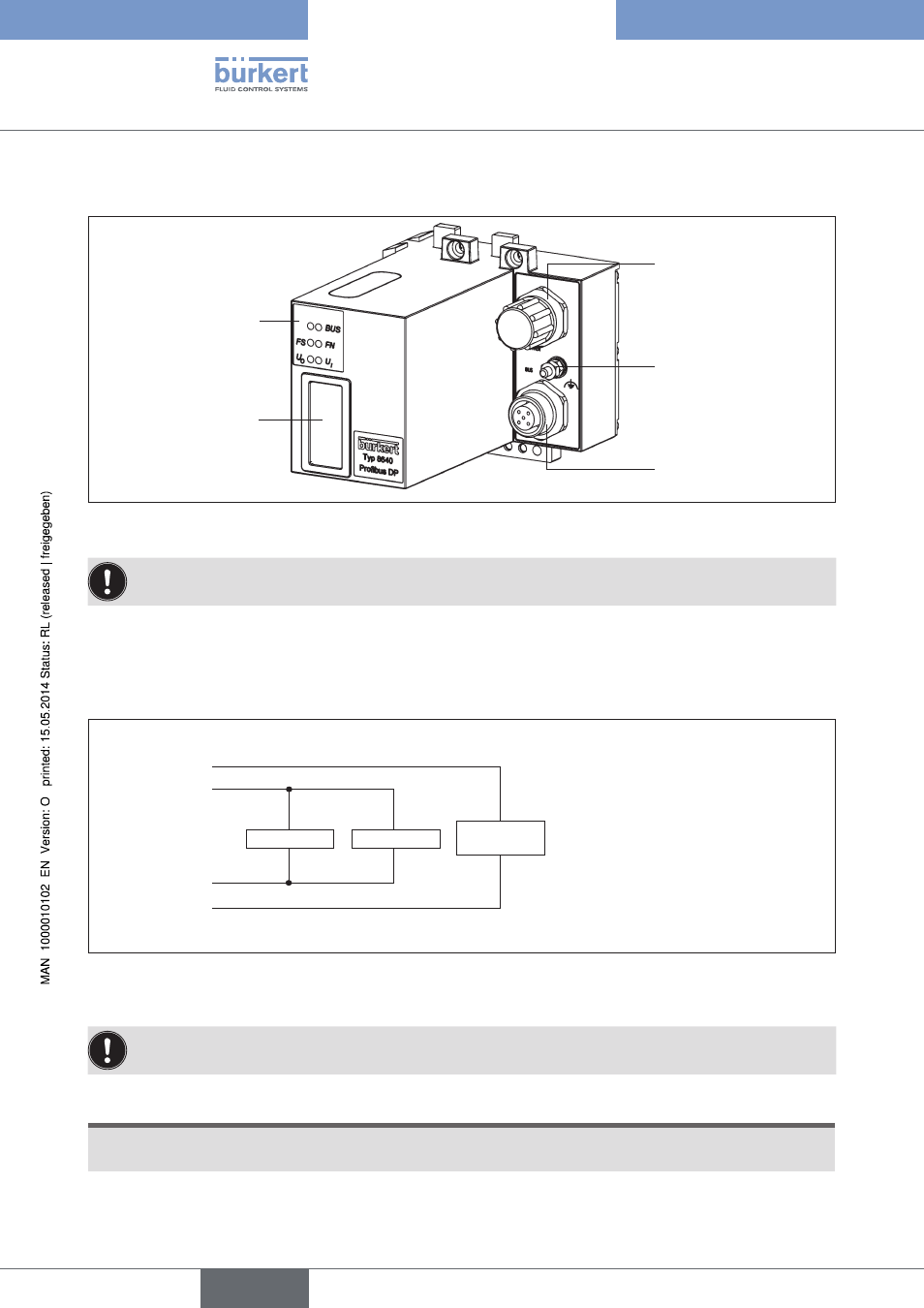
PROFIBUS DP/V1, IP54 - overview
Power Supply
Functional earth
Field bus connection
DIP Switches
LED Status Display
Figure 9:
Overview field bus module PROFIBUS-DP IP54
The DIP switches can be operated through the covering film.
8.2.1.
Power supply IP54
The 4-pole circular plug-in connector for the power supply is configured as follows:
Electronics
Inputs
Valves /
Outputs
24 V DC (1)
valves /
outputs
24 V DC (2)
logic
GND (3)
logic
GND (4)
valves /
outputs
Pin 1: +24 V - valves (outputs)
Pin 2: +24 V - logic + inputs
Pin 3: GND - logic + inputs
Pin 4: GND - valves (outputs)
Figure 10:
Power supply configuration
Pin 1 of the power supply must be supplied with a 4 A medium time-lag fuse; Pin 2 with 1 A.
NOTE!
To ensure electromagnetic compatibility (EMC) connect the screw terminal FE (functional earth) to earth
potential using a short cable (30 cm).
english
Type 8640
- Type 0125 (15 pages)
- Type 0121 (4 pages)
- Type 0330 (2 pages)
- Type 0331 (4 pages)
- Type 6012 (4 pages)
- Type 0127 (18 pages)
- Type 0131 (5 pages)
- Type 0141 (5 pages)
- Type 0142 (12 pages)
- Type 0145 (3 pages)
- Type 0174 (5 pages)
- Type 0212 (2 pages)
- Type 0211 (5 pages)
- Type 0212-B (18 pages)
- Type 0250 (64 pages)
- Type 0253 (2 pages)
- Type 0255 (15 pages)
- Type 0355 (2 pages)
- Type 0255 (2 pages)
- Type 8006 (34 pages)
- Type 8640 (2 pages)
- Type 8640 (55 pages)
- Type 0256 (15 pages)
- Type 0256 (2 pages)
- Type 0258 (72 pages)
- Type 0262 (5 pages)
- Type 0273 (6 pages)
- Type 0280 (5 pages)
- Type 0280 (2 pages)
- Type 0280 (12 pages)
- Type 0281 (2 pages)
- Type 0282 (2 pages)
- Type 0283 (2 pages)
- Type 0286 (4 pages)
- Type 0287 (15 pages)
- Type 0290 (2 pages)
- Type 0290 (14 pages)
- Type 0293 (18 pages)
- Type 0300 (6 pages)
- Type 0301 (6 pages)
- Type 0311 (2 pages)
- Type 0312 (6 pages)
- Type 6518 (57 pages)
- Type 6519 (3 pages)