Mode inputs, Normal mode, Shifted inputs mode – Burkert Type 8640 User Manual
Page 42: Input module (e.g. 16-fold), English
42
9.3.
Mode inputs
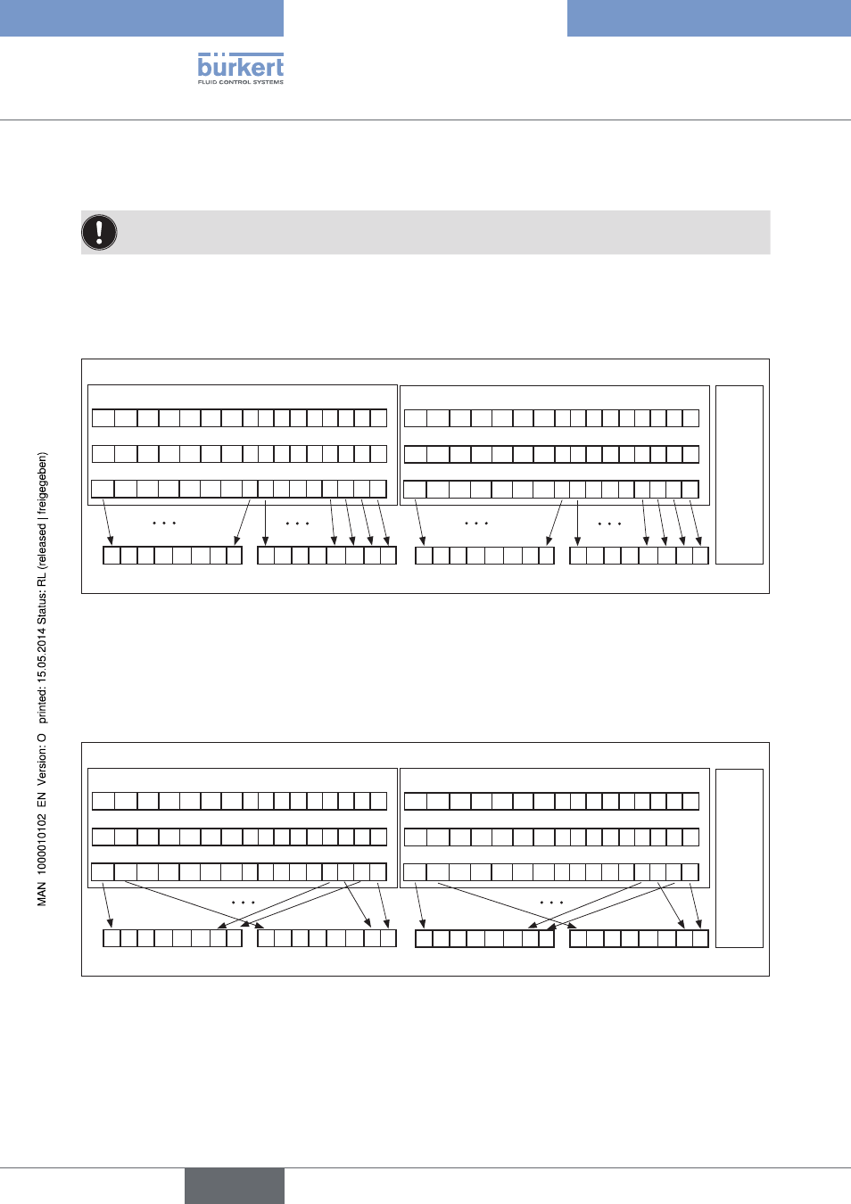
With the help of the input modes the inputs (repeaters) can be assigned diversely in the process image of
the outputs (PAE). The mode selection takes place in the parameter telegram.
9.3.1.
Normal mode
In normal mode all outputs are read in from right to left.
Extension module
inputs
16
15
14
13 12 11 10
9 8 7
6
5 4 3
2
1
Power supply earth
Power supply +24 V
Inputs
8
7
6
5
4
3
2
1
8
7
6
5
4
3
2
1
16
15
14
13 12 11 10
9 8 7
6
5 4 3
2
1
Power supply earth
Power supply +24 V
Inputs
8
7
6
5
4
3
2
1
8
7
6
5
4
3
2
1
EME 32
Input module (e.g. 16-fold)
Input module (e.g. 16-fold)
Byte 3
Byte 1
Byte 0
Byte 2
Figure 20:
Normal mode
9.3.2.
Shifted inputs mode
In shifted inputs mode the first 16 inputs are placed alternatingly in byte 0 and byte 1 of the transmission log. The
same procedure is carried out for the following 16 inputs with byte 2 and byte 3.
Extension module
inputs
16
15
14
13 12 11 10
9 8 7
6
5 4 3
2
1
Power supply earth
Power supply +24 V
Inputs
8
7
6
5
4
3
2
1
8
7
6
5
4
3
2
1
16
15
14
13 12 11 10
9 8 7
6
5 4 3
2
1
Power supply earth
Power supply +24 V
Inputs
8
7
6
5
4
3
2
1
8
7
6
5
4
3
2
1
EME 32
Input module (e.g. 16-fold)
Input module (e.g. 16-fold)
Byte 3
Byte 1
Byte 0
Byte 2
Figure 21:
Shifted inputs mode
Configurationandparameter
settingsforPROFIBUSDP
english
Type 8640