Audio input level, Adjustment lighting table – Extron Electronics SMX System User Guide User Manual
Page 34
SMX System MultiMatrix Switcher • Operation
28
INPUTS
1 2 3 4 5 6 7 8 9 10 11 12 13 14 15 16
OUTPUTS
1 2 3 4 5 6 7 8 9 10 11 12 13 14 15 16
INPUTS
1 2 3 4 5 6 7 8 9 10 11 12 13 14 15 16
OUTPUTS
1 2 3 4 5 6 7 8 9 10 11 12 13 14 15 16
Step 1 – Press and release Esc.
Flashes green once and clears pending changes
.
I/O PLANE SELECT
1 2 3 4 5 6 7 8 9 10 11 12 13 14 15
0
Plane button lights red, indicating an audio (signal) plane.
Step 2 – Press audio I/O plane button to be adjusted (here button 4).
INPUTS
1 2 3 4 5 6 7 8 9 10 11 12 13 14 15 16
OUTPUTS
1 2 3 4 5 6 7 8 9 10 11 12 13 14 15 16
I/O button 1 lights
red.
Step 3 – Press and hold any I/O plane button until audio plane button flashes.
Selected audio plane button flashes
red and I/O button turns off.
I/O PLANE SELECT
1 2 3 4 5 6 7 8 9 10 11 12 13 14 15
0
INPUTS
1 2 3 4 5 6 7 8 9 10 11 12 13 14 15 16
OUTPUTS
1 2 3 4 5 6 7 8 9 10 11 12 13 14 15 16
I/O button momentarily lights
red until audio plane button flashes. I/O button 1 turns off.
Step 4 – Press the button for the input needing the audio level adusted (here 8).
Selected input button lights
green, and View button lights red.
The current audio level dB is indicated by the lit and flashing output buttons.
Here buttons 1-4 lit and 5 flashing
red indicates an input level of -9 dB.
(See
Figure 25
for button lighting and dB levels.)
ENTER
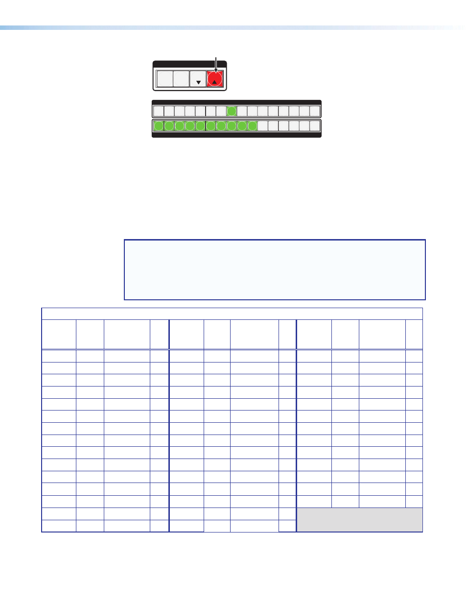
Step 5 – Press and hold View to decrease or Esc to increase audio level.
Selected control button lights
red (in this example, Esc was pressed).
C O N T R O L
PRESET
ESC
VIEW
Selected input button remains lit. Outputs light, flash, or go out as the level changes.
Here the dB is raised to +20 dB. Outputs 1-10 are lit
green.
Additional inputs can be adjusted by repeating steps
4 and 5.
Step 6 – Press Enter to leave the input audio level adjustment mode.
All buttons go out.
NOTE: View button lights red and output buttons are red when current audio
level is negative dB, and Esc button lights
red and output buttons are
green when it is positive dB.
Figure 25.
Adjusting the Input Audio Levels — an Example (Steps 5 and 6)
6.
If desired, select additional inputs can be set by pressing their input button.
7.
Press and release the Enter button (or wait 30 seconds) to exit the audio display and
adjustment mode. The audio plane button extinguishes.
NOTE: There is only one audio level setting per input on a specific plane. It is shared by
the left and right audio inputs. The audio levels are stored in non-volatile memory. When
power is removed and restored, they are retained.
If the audio is set to “follow-all” upon initial selection in step
2, the I/O plane and
associated input and output buttons light amber. When an input or output button is held
for 2 seconds (step
3), the I/O plane button flashes red.
Audio Input Level Adjustment Lighting
dB
Level
Color
Buttons
Lit or
Flashing
+/-
dB
Level
Color
Buttons Lit
or Flashing +/-
dB
Level
Color
Buttons Lit
or Flashing +/-
24
green
12
>
9
green
5 flash
>
-6
red
3 flash
<
23
green
12 flash
>
8
green
4
>
-7
red
4 flash
<
22
green
11
>
7
green
4 flash
>
-8
red
4 flash
<
21
green
11 flash
>
6
green
3
>
-9
red
5 flash
<
20
green
10
>
5
green
3 flash
>
-10
red
5 flash
<
19
green
10 flash
>
4
green
2
>
-11
red
6 flash
<
18
green
9
>
3
green
2 flash
>
-12
red
6 flash
<
17
green
9 flash
>
2
green
1
>
-13
red
7 flash
<
16
green
8
>
1
green
1 flash
>
-14
red
7 flash
<
15
green
8 flash
>
0
not lit
-15
red
8 flash
<
14
green
7
>
-1
red
1 flash
<
-16
red
8 flash
<
13
green
7 flash
>
-2
red
1 flash
<
-17
red
9 flash
<
12
green
6
>
-3
red
2 flash
<
-18
red
9
<
11
green
6 flash
>
-4
red
2 flash
<
10
green
5
>
-5
red
3 flash
<