Creating ties, An example of creating an input to output tie – Extron Electronics SMX System User Guide User Manual
Page 23
SMX System MultiMatrix Switcher • Operation
17
•
If any associated (lit) output button (an existing tie) is toggled off by pressing the button
and the Enter button is pressed, the existing tie to that output is lost.
•
Ties can be made using SIS commands via RS-232, RS-422, Ethernet, the SMX
Control Software program, or the internal Web pages (see
on page 34 for RS-232 and RS-422 control,
on
page 59 for Software, or
HTML Configuration and Control
on page 87 for HTTP
methods).
Creating Ties
To make input ties to untied outputs:
An example of creating an input to output tie
The following shows how to create a tie (input 7 on plane 0 to output 4 in this example).
1.
Press and release the Esc button to clear any pending input, output, or control button
changes. The Esc button flashes green once.
2.
Press and release the I/O Plane Select button for the desired configuration.
NOTE: The I/O Plane button and Input button 1 lights, indicating the signal type:
green for video, red for audio, or amber for both video and audio signals. In the
examples below, the plane carries a video signal only.
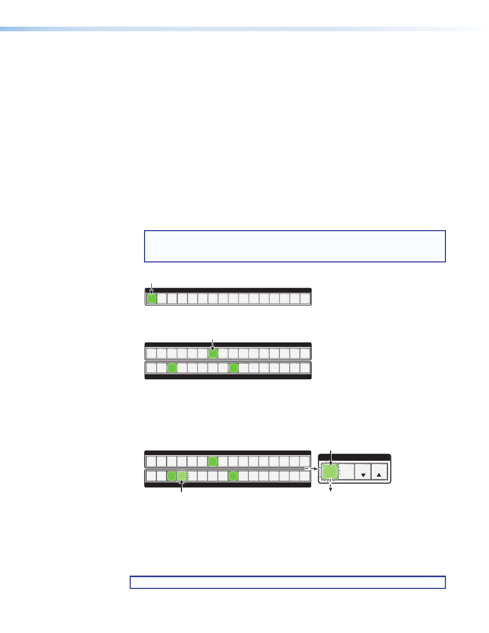
Step 2.
Press and release the desired I/O Plane Select button.
I/O PLANE SELECT
1 2 3 4 5 6 7 8 9 10 11 12 13 14 15
0
I/O plane and Input buttons light
green if on a video plane, red if on
an audio plane,
or
amber if on a video and audio plane.
INPUTS
1 2 3 4 5 6 7 8 9 10 11 12 13 14 15 16
OUTPUTS
1 2 3 4 5 6 7 8 9 10 11 12 13 14 15 16
Step 3.
Press desired Input button (lights).
Currently tied outputs light according to the signal type of the output.
Input 1 extinguishes.
Step 4.
Press and release the desired output button (flashes).
INPUTS
1 2 3 4 5 6 7 8 9 10 11 12 13 14 15 16
OUTPUTS
1 2 3 4 5 6 7 8 9 10 11 12 13 14 15 16
The Enter button also flashes (
green).
ENTER
Step 5.
Press and release Enter.
All buttons extinguish
.
C O N T R O L
PRESET
ESC
VIEW
Figure 10.
Select I/O Plane, then an Input — an Example (Steps 2 and 3)
3.
Press and release the desired input button (see figure 10). This button lights according
to the plane signal type: green (video), red (audio), or amber (both).
Step 2.
Press and release the desired I/O Plane Select button.
I/O PLANE SELECT
1 2 3 4 5 6 7 8 9 10 11 12 13 14 15
0
I/O plane and Input buttons light
green if on a video plane, red if on
an audio plane,
or
amber if on a video and audio plane.
INPUTS
1 2 3 4 5 6 7 8 9 10 11 12 13 14 15 16
OUTPUTS
1 2 3 4 5 6 7 8 9 10 11 12 13 14 15 16
Step 3.
Press desired Input button (lights).
Currently tied outputs light according to the signal type of the output.
Input 1 extinguishes.
Step 4.
Press and release the desired output button (flashes).
INPUTS
1 2 3 4 5 6 7 8 9 10 11 12 13 14 15 16
OUTPUTS
1 2 3 4 5 6 7 8 9 10 11 12 13 14 15 16
The Enter button also flashes (
green).
ENTER
Step 5.
Press and release Enter.
All buttons extinguish
.
C O N T R O L
PRESET
ESC
VIEW
Figure 11.
Select the Outputs, then Press Enter — an Example (Steps 4 and 5)
4.
Press and release the output buttons (see figure 11). The selected output buttons flash.
The enter button flashes green.
5.
Press and release the Enter button to make the tie. The plane selection, input, output,
and Enter buttons all extinguish.
NOTE: Repeat steps 2 through 5 if the Enter button extinguishes before being pressed.