Extron Electronics SMX System User Guide User Manual
Page 17
SMX System MultiMatrix Switcher • Installation and Cabling
11
NOTES:
•
The boards are hot-swappable: they can be installed or removed without turning
off or disconnecting the power. However, turning the power off prior to installing or
removing boards is recommended.
•
Use ESD precautions when installing a board to avoid damaging it. Keep the
board in the anti-static bag until needed. Use proper grounding techniques during
installation.
See
Frames and I/O Boards
on page 114 for a full list of available boards for the SMX.
Installing new boards into an empty SMX frame
1.
Remove as many of the blanks plates from the rear of the unit as needed.
2.
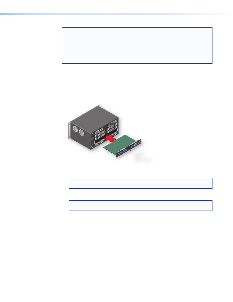
When ready, remove the board from the anti-static bag, taking care not to touch any
of the components on the board. Slide the board into the open rear slot (see figure 4),
carefully aligning it with the plastic slides in the frame. Push the board firmly into place.
RESET
RS
232
/RS
422
REMO
TE
LAN
AC
T
LINK
50-
60H
z
100
-24
0V
1.3
A M
AX
.
US
LIS
TED
17
TT
AU
DIO
/VID
EO
AP
PAR
ATU
S
®
1
5
tx rx
tx
3
tx rx
7
tx
2
6
tx rx
tx
4
tx rx
8
tx
PL
AN
E A
DR
ES
S
DIGI
TAL
VID
EO
SDI / HDSDI OUTPUT
S
8
7
1
4
5
6
3
2
SDI / HDSDI INPUTS
8
7
1
4
5
6
3
2
PL
AN
E A
DR
ES
S
INPUTS
1
2
3
4
OUTPUT
S
1
2
3
4
PL
AN
E A
DR
ES
S
COMPUTER IN
5
6
7
8
1
2
3
4
COMPUTER OU
T
5
6
7
8
1
2
3
4
PL
AN
E A
DR
ES
S
VIDEO OUTPUTS
16
15
9
12
13
14
11
10
VIDEO INPUTS
16
15
9
12
13
14
11
10
16
15
9
12
13
14
11
10
16
15
9
12
13
14
11
10
S-VIDE
O
Y
C
Y
C
Y
C
IN
PL
AN
E A
DR
ES
S
9
10
11
12
13
14
15
16
L
R
L
R
L
R
L
R
L
R
L
R
L
R
L
R
L
1
R
L
2
R
L
3
R
L
4
R
L
5
R
L
6
R
L
7
R
L
8
R
I
N
P
U
T
S
I
N
P
U
T
S
9
10
11
12
13
14
15
16
L
R
L
R
L
R
L
R
L
R
L
R
L
R
L
R
L
1
R
L
2
R
L
3
R
L
4
R
L
5
R
L
6
R
L
7
R
L
8
R
O
U
T
P
U
T
S
O
U
T
P
U
T
S
Optional
Board
(audio shown)
Figure 4.
SMX Frame Rear Showing Board Installation
3.
Tighten down the screws on each end of the board.
NOTE: Use a tool to fully tighten the screws after initial installation and subsequent
removal and replacement of the boards.
4.
Repeat steps
1 through 3 for all boards needing installation.
NOTE: If the unit is connected via RS-232 or RS-422, it responds with
Reconfig
when a board is installed or replaced.
The SMX is now ready for cabling (see
Replacing an existing I/O board
1.
Remove any input and output cables for the I/O board being replaced.
2.
Loosen the outer screws on the existing board and remove it from the unit.
3.
Slide the replacement board firmly into place and tighten down the screws.
4.
Repeat for all boards to be replaced. Any new boards are now ready for cabling.
To configure the SMX with the new cards, see
on page 13. For alternative
configuration methods for the SMX, see
on page 34,
HTML Configuration and Control
on page 87.