4 antenna connection – Xylem SDI-12 Data Logger iRIS 220, iRIS 320, iRIS 350, iRIS 150, iRIS 300 User Manual
Page 85
79
iQuest (NZ) Ltd - PO Box 15169, Hamilton, New Zealand Tel: +64 7 857-0810 Fax: +64 7 857-0811 Email: [email protected]
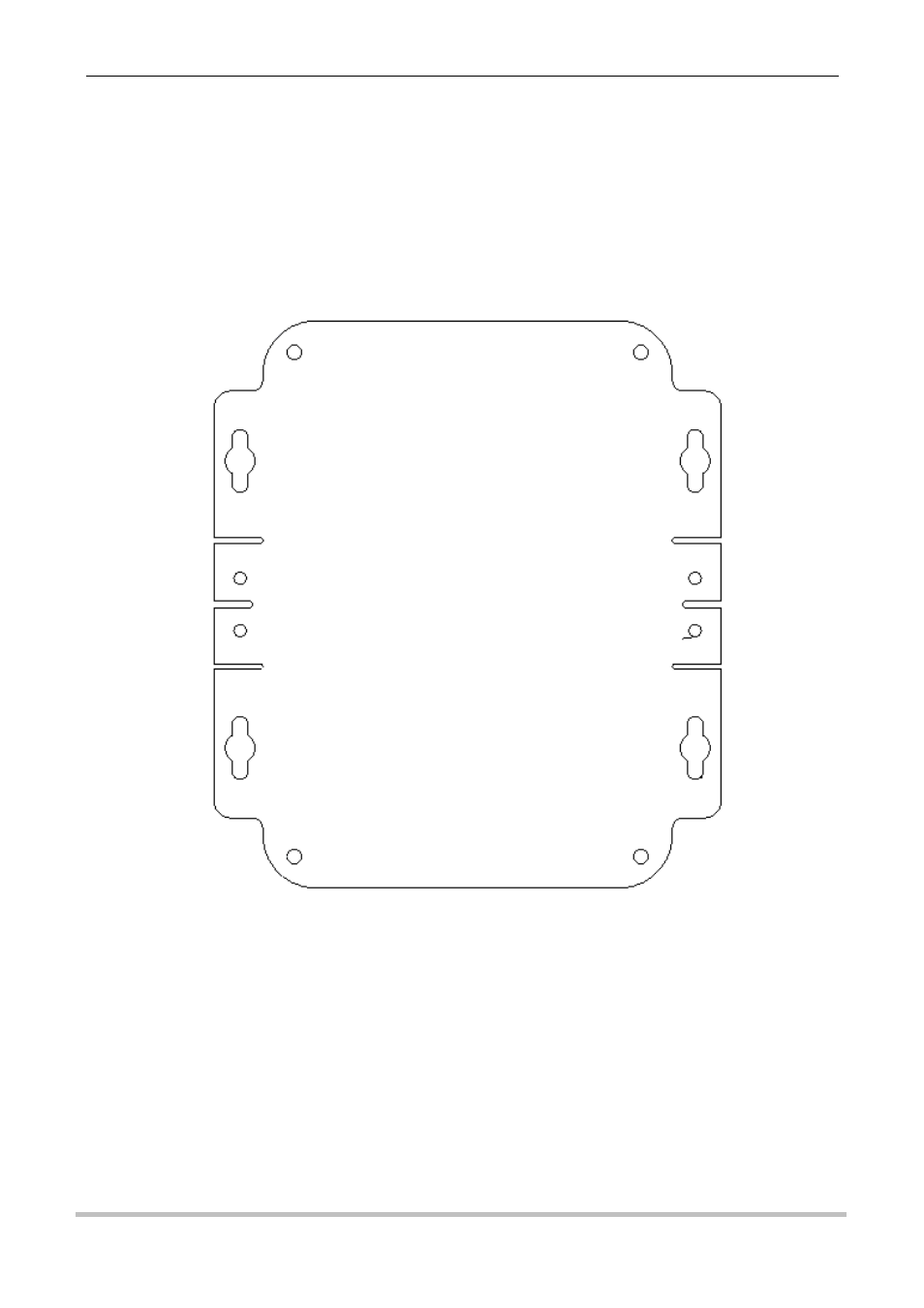
13.3 Mounting – iRIS 320 / iRIS 320V
An outline of the iRIS 320 mounting plate is shown below. The recommended mounting screws are M4
machine screws or Twinfast® wood screws.
NOTE: It is very important that the three M5 Allen Key® screws on the front panel are tightened firmly
after installation to maintain the IP65 rating of the enclosure.
Figure 18 - iRIS 320 / iRIS 320V Mounting Diagram
The mounting holes are on 130mm (5.11in) width by 82mm (3.22in) height centres.
13.4 Antenna Connection
The iRIS 320 / iRIS 320V antenna is fitted through a compression gland in the bottom of the case. Internally,
the antenna terminates at a female BNC connector on the circuit board.
In areas of good signal strength, a small “stubby” or omni-directional type antenna will suffice. In areas of
more marginal coverage, the antenna should an external high gain type such as a Yagi, via appropriate low-
loss high frequency coaxial cable and male SMA connector.