Xylem SDI-12 Data Logger iRIS 220, iRIS 320, iRIS 350, iRIS 150, iRIS 300 User Manual
Page 34
iRIS Datalogger User Guide V1.50
28
iQuest (NZ) Ltd - PO Box 15169, Hamilton, New Zealand Tel: +64 7 857-0810 Fax: +64 7 857-0811 Email: [email protected]
Sensor Cfg (Level 3)
The Sensor Cfg menu is used to configure each of the six main virtual sensors. Internal Sensors (7-9)
provide a smaller sub-set of these settings as most of the parameters are known and fixed. Refer to the
datalogging features (Section 2.3.5) of this manual for a discussion on datalogging and virtual sensors. This
menu option also shows the current scaled measurement value for the selected sensor.
Analog sensors also show the actual measured voltage as well.
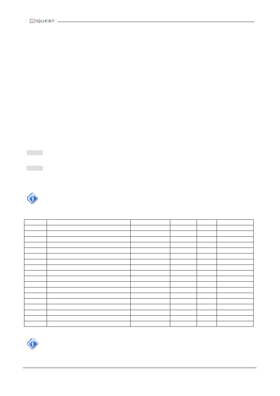
* Sensor 1 Cfg
(Now: 1.9620) [0.7218V]
0 Exit
1 Source [1: Analog 1]
2 Name [Water Lvl]
3 Mode [Period Avg+Min+Max]
4 Multiplier [ 0.001]
5 Offset [ 0.0000]
6 Log Multiplier [1000]
7 Log Rate [15min]
8 Alarms
9 Data
>
Option 0
Select this option to return to the main Sensor Cfg menu.
Option 1
When this option is selected you will be prompted to enter a number representing the source from which the
virtual sensor should acquire its data. Use zero to disable the sensor. Valid data sources are shown in the
table below.
Analog inputs 3 and 4 will give a value of zero on iRIS 220/320 units with V1.1 revision
hardware. Analog inputs on the iRIS 220/320 will give a value in millivolts (0-5000mV).
> Source (0.15)=
Source
Description
Raw Range
Multiplier Offset
Log Multiplier
0
Unused / disabled
N/A
N/A
N/A
N/A
1
Analog Input 1
0 to 5.0000
2
Analog Input 2
0 to 5.0000
3
Analog Input 3
0 to 5.0000
4
Analog Input 4
0 to 5.0000
5
Pulse Counter on Digital Input 1
0 to 1
6
Pulse Counter on Digital Input 2
0 to 1
7
Auto Pulse Counter on Digital Input 1
0 to 1
8
Auto Pulse Counter on Digital Input 2
0 to 1
9
Frequency Counter on Digital In 1
0 to 5000Hz
10
Frequency Counter on Digital In 2
0 to 5000Hz
11
Up/Down Counter on Digital Ins 1 & 2 -32768 to 32767
12
High-speed Serial Instrument
-32768 to 32767
13
Database Location
-32768 to 32767
14
Received Signal Strength
0 to 31 (or 99)
1
0
1
15
SDI-12
16
Quadrature Shaft encoder
-32768 to 32767
17
DC power availability status
0 to 1
1
0
1
Table 3 - Standard Sensor Sources
Sensors 7-9 are reserved for the internal parameters and therefore do not require manual set-
up apart from the log rate and alarm settings. For completeness, the internal configuration is
shown on the next page.