External 12v battery (optional) – Xylem SDI-12 Data Logger iRIS 220, iRIS 320, iRIS 350, iRIS 150, iRIS 300 User Manual
Page 64
iRIS Datalogger User Guide V1.50
58
iQuest (NZ) Ltd - PO Box 15169, Hamilton, New Zealand Tel: +64 7 857-0810 Fax: +64 7 857-0811 Email: [email protected]
6.9.2 iRIS 220 / iRIS 320 Installation
NOTE: Using this type of encoder on the older iRIS 220 / iRIS 320 requires iRIS hardware (PCB Rev
1.2, four analog inputs), firmware version VN/2.23 or later and software V1.23 or later.
A commonly used type of digital water level instrument is one that provides two pulse outputs, the direction
of movement being determined by the phase difference between the two signals. The iRIS tracks these
steps and therefore the relative water level.
These instruments are passive and do not require a power supply. This implementation makes use of a
digital input (DI2) as the reference channel and an analog input (AIN4), which is used as a simulated digital
input, as the auxiliary channel. This scenario leaves DI1 free for use with another sensor such as a rain
gauge or flow meter.
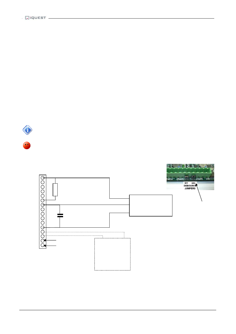
The diagram below shows the connections for such an installation. Normally, the A output is connected to
DI2 and the B output to AIN4. A 2K2 resistor must be connected between the 5VOP terminal and the AIN4
terminal to provide the supply for the simulated digital input. In addition a 100nF capacitor must be fitted
between the DI2 terminal and the DGND terminal to reinstate the debounce function that is disabled by
removing the link as mentioned below. The resistor and capacitor do not need to be precision types.
If the direction is incorrect, reverse the two channels.
The debounce link for DI2 must be removed for correct operation, especially with instruments
such as the HS AD150 that have an in-built 1K current limit resistor. The debounce link also
enables a dc source that will cause problems with the simulated digital input on AIN4 if it is left
connected.
TOP
iRIS 220 / 320 I/O Connector
BOTTOM
Remove
this jumper
- +
External
12V Battery
(Optional)
B
Quadrature
A
Shaft
Encoder
COM
Charging source
e.g. solar panel
AI4
AI3
AI2
AI1
AGND
5VOP
DI2
DI1
DO2
DO1
SDI-12
DGND
12V+
GND (-)
VIN+
GND (-)
4K7 ¼ w
5% resistor
100nF 50V
capacitor