3 connecting a 0-5v pressure transducer – Xylem SDI-12 Data Logger iRIS 220, iRIS 320, iRIS 350, iRIS 150, iRIS 300 User Manual
Page 57
51
iQuest (NZ) Ltd - PO Box 15169, Hamilton, New Zealand Tel: +64 7 857-0810 Fax: +64 7 857-0811 Email: [email protected]
6.3 Connecting a 0-5V Pressure Transducer
Connecting a standard sensor (such as a pressure transducer that provides a 0-5V signal) to an iRIS is
relatively straightforward. The sensor can be powered from the iRIS’s 12V supply and optionally controlled
by a digital output to save power.
However, the iRIS’s internal battery is NOT recommended for directly powering the sensor alone if the
charging source is a solar panel, as it is a relatively low capacity type. Connect a supplementary external
12V battery (7A/Hr or larger) to increase the available storage.
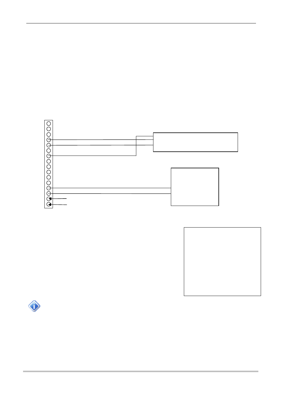
The diagram below shows the typical connection diagram for such an installation. It assumes the use of AI1
as the desired input channel. It also shows the connection of the switched supply from DIO4.
TOP
iRIS I/O Connector
The sensor should be configured for the correct channel, scaling and logging regime as described in Section
4.4.8. Also, see Section 8 for a description of how to accurately scale the sensor.
A typical sensor configuration example for this type of installation is
shown here. The instrument is a 10 metre, 0-5V output pressure
transducer. The level is averaged and the result logged every 15
minutes.
The iRIS supports activation of one or both digital outputs with a schedule. See Section
4.4.11 for more details and an example. Therefore, if further power reduction is to be
achieved by controlling the transducer power, follow this procedure:
1.
Connect the transducer supply to the switched 12V output (DIO4 on the iRIS 350 or DO2 on
the iRIS 220/320)
2.
Configure the digital output’s mode to be Schedule (Mode = 1).
3.
Set up the digital output’s schedule to match the sensor’s logging period, but with the digital
output being set to activate the desired amount of time before the sensor is to log and with
sufficient “on” time to ensure an overlap with the logging time.
4.
Ensure the sensor mode is set to Instant (0) or 1 minute average (4).
AI4
AI3
AI2
AI1
AGND
AOUT
DIO4
DIO3
DIO2
DIO1
SDI-12
DGND
12V+
GND (-)
VIN+
GND (-)
+
Signal
Pressure Transducer
-
Charging source e.g. solar panel
12V Battery
(Required)
+
-
* Sensor 1 Cfg
(Now: 6.2454 [3.1226V]
0 Exit
1 Source [1: Analog1]
2 Name [Water Lvl]
3 Mode [Period Avg]
4 Multiplier [ 2.0000]
5 Offset [ 0.0000]
6 Log Multiplier [1000]
7 Log Rate [15min]
8 Alarms
9 Data