7 using ilink’s sensor configuration tool, 1 iris sensor configuration example – Xylem SDI-12 Data Logger iRIS 220, iRIS 320, iRIS 350, iRIS 150, iRIS 300 User Manual
Page 68
iRIS Datalogger User Guide V1.50
62
iQuest (NZ) Ltd - PO Box 15169, Hamilton, New Zealand Tel: +64 7 857-0810 Fax: +64 7 857-0811 Email: [email protected]
7 Using iLink’s Sensor Configuration Tool
To optimise the process of maintaining multiple iRIS installations with the same (or similar) sensor
configuration, iLink includes a graphical configuration tool. This allows the configuration of any the sensors to
be changed, sent to the logger or saved to disk. It also supports the retrieval of sensor settings from the
logger and from disk. This means that setting up new loggers is made very simple as a common
configuration file can be sent to each logger.
7.1 iRIS Sensor Configuration Example
This example shows how to set up a simple iRIS sensor configuration to measure water level from an
SDI-12 sensor and also log internal battery voltage. This example is valid for all models
1. Connect to the iRIS using iLink.
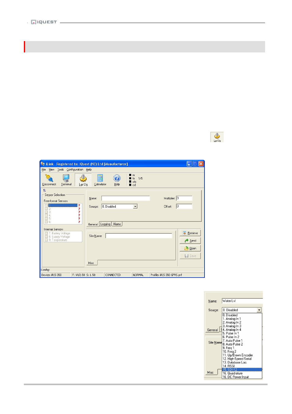
2. Invoke the iRIS configuration form by clicking the Logger Cfg tool button
or by selecting the menu item Configuration->iRIS Logger Configuration. This will bring up the iRIS
Sensor Configuration form as shown here.
3. Next, set up the water level sensor. Enter the sensor name “Water Lvl” (max 10 characters).
4. Now set the sensor source from the drop down list. Select source 15,
SDI-12. Then enter the correct SDI-12 instrument address and
variable. In our example the instrument has an address of zero (0) and
we require the first value (variable 1).