External 12v battery (optional) – Xylem SDI-12 Data Logger iRIS 220, iRIS 320, iRIS 350, iRIS 150, iRIS 300 User Manual
Page 60
iRIS Datalogger User Guide V1.50
54
iQuest (NZ) Ltd - PO Box 15169, Hamilton, New Zealand Tel: +64 7 857-0810 Fax: +64 7 857-0811 Email: [email protected]
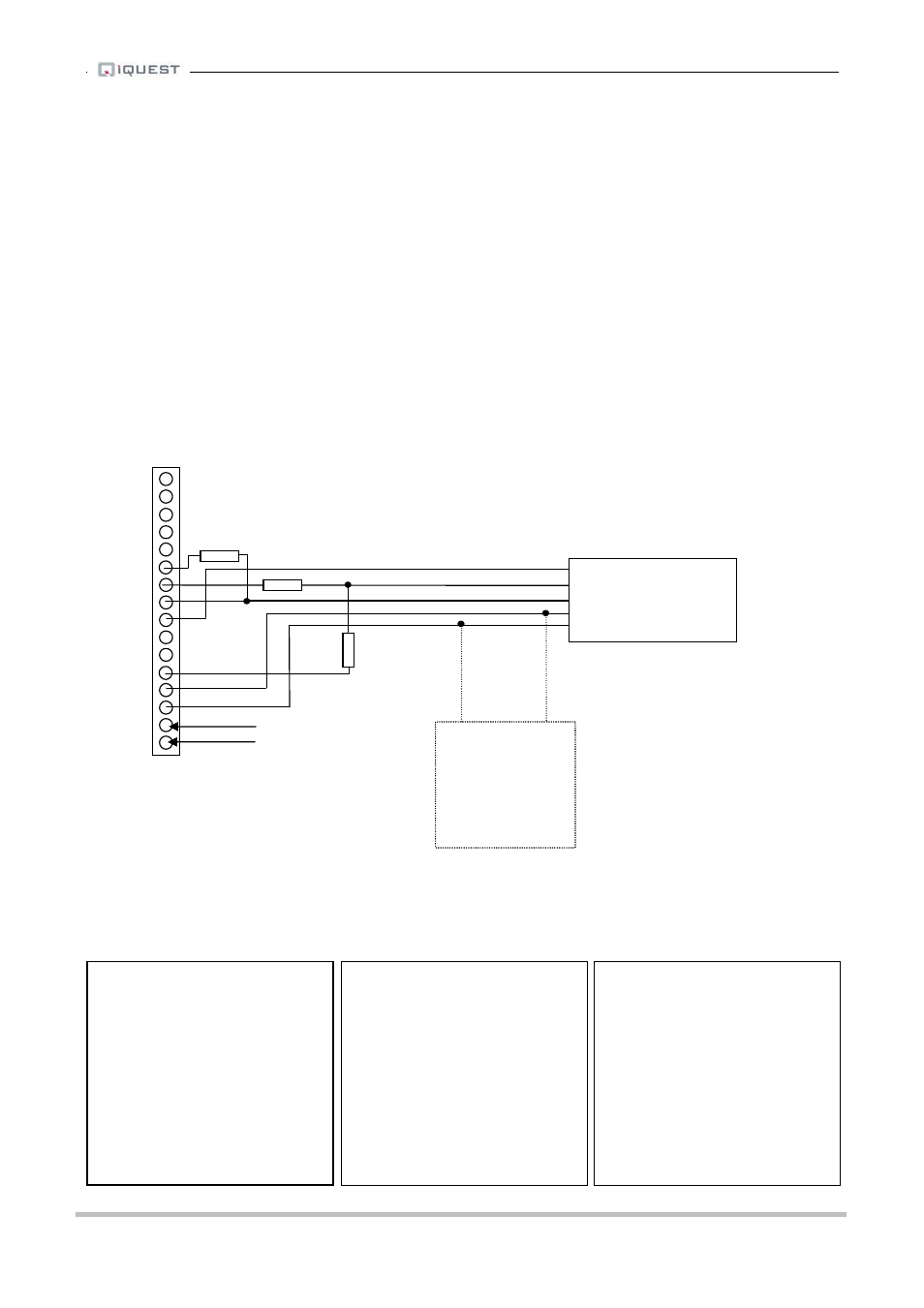
6.6 Connecting a Unidata High-Speed Serial Instrument
Unidata high-speed serial instruments are supported by the iRIS, but with some conditions.
1.
Only 16 bit (two-byte) instruments can be used. Most water level encoders are of this type.
2.
A small hardware adaptor is required to interface the iRIS I/O to the instrument. This adaptor
comprises three 4K7 resistors as shown in the diagram.
The Unidata instruments normally require a 12V supply and this is readily obtained from the iRIS. A
supplementary 12V battery can be connected if desired. Typically, this type of instrument requires very little
current, so the internal iRIS battery will normally suffice. The diagram below shows the required connections
for such an installation. The connections must be done as listed.
Instrument
iRIS
SYNC
DIO1 with a 4K7 pull-up resistor to AOUT terminal (5VOP on iRIS 220/320)
CLOCK
DIO2 with two 4K7 resistors to adjust the voltage levels
DATA
DI2
TOP
iRIS I/O Connector
*
BOTTOM
A typical sensor configuration example for this type of installation is shown below. The instrument is a
Unidata 6809 serial water level encoder. The level in metres is averaged and the result logged every 15
minutes. The digital outputs are used to enable and clock the sensor. Output 1 should be disabled and
output 2 set to permanently on. The digital outputs configuration is also shown below.
* Sensor 1 Cfg
(Now: 0.0)
0 Exit
1 Source [12: HS SerI]
2 Name [Water Lvl]
3 Mode [Period Avg]
4 Multiplier [ 0.001]
5 Offset [ 0.000]
6 Log Multiplier [1000]
7 Log Rate [15min]
8 Alarms
9 Data
* Digital Output 1 Cfg
0 Exit
1 Enable [No]
2 Polarity [Normal]
3 Mode [0: Link]
4 Duration [0 sec]
5 Frequency [0 min]
6 Start Time [0000]
7 End Time [0000]
* Digital Output 2 Cfg
0 Exit
1 Enable [Yes]
2 Polarity [Normal]
3 Mode [5:Permanent ON]
4 Duration [0 sec]
5 Frequency [0 min]
6 Start Time [0000]
7 End Time [0000]
AI4
AI3
AI2
AI1
AGND
AOUT
DIO4
DIO3
DIO2
DIO1
SDI-12
DGND
12V+
GND (-)
VIN+
GND (-)
- +
External
12V Battery
(Optional)
DATA
CLK
Unidata Serial
SYNC
Instrument
+12V
0V
Charging source
e.g. solar panel
All Resistors
4K7 5%