4 analog i/o – Xylem SDI-12 Data Logger iRIS 220, iRIS 320, iRIS 350, iRIS 150, iRIS 300 User Manual
Page 16
iRIS Datalogger User Guide V1.50
10
iQuest (NZ) Ltd - PO Box 15169, Hamilton, New Zealand Tel: +64 7 857-0810 Fax: +64 7 857-0811 Email: [email protected]
3.5.4 Analog I/O
Analog Inputs
On the iRIS 350, the four analog inputs are uni-polar 0-5Vdc with 16-bit resolution. Each input presents a
load impedance of 97K to the input signal. The iRIS 220 and iRIS 320 have 12-bit resolution inputs with an
impedance of 98 K.
For the iRIS 350, scaling factors should be chosen to convert from a raw value of 0.0000 – 5.0000, which
reflects the input signal range of 0-5V. When current sources such as 0-20mA or 4-20mA are connected, an
internal sink resistor (100) is enabled by an internal user-settable link. In this mode the actual voltage range
is 0-2V and the scaling factor should take this into account.
As the analog inputs have an input impedance of 97K, the actual sink resistor impedance
will be slightly lower than the value fitted. When, for example, the current mode link is fitted, a
sink resistor of 100 ohms is installed. The actual impedance will theoretically be 99.71;
therefore the voltage measured by the iRIS will also be slightly lower than expected. See
Section 8 for details on the analog input scaling method to use to optimise the calibration.
Figure 3 - Simplified iRIS 350 Analog Input Circuit
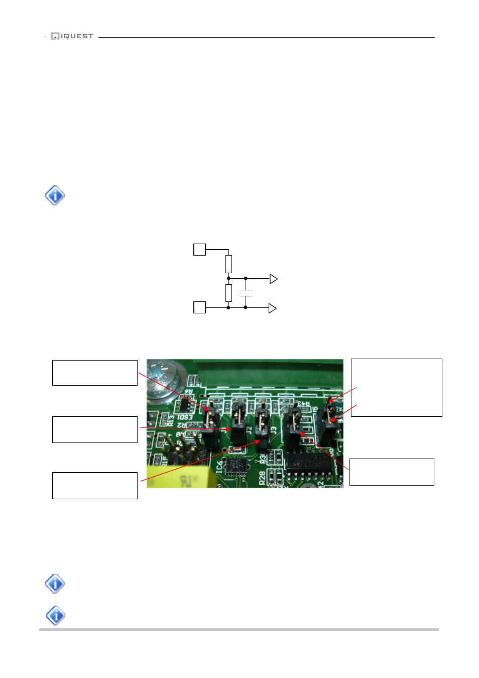
Figure 4 - iRIS 350 Analog Input / Output Links
Analog Output
The iRIS 350 has a single variable analog output. This may be configured to deliver either a voltage output
ranging between 0-5V or a current output ranging from 0-20mA or 4-20mA. The output mode is link
selectable.
In the current software this output is fixed to 5V output making it compatible with the fixed 5V
excitation output on the iRIS 220/320.
See Section 2.4 for a list of the I/O differences between the models.
1nF
22K
75K
AGND
AINx
To ADC
AIN4 100
Ω current
sink enable link (J1)
AIN1 100
Ω current
sink enable link (J4)
AIN3 100
Ω current
sink enable link (J2)
AIN2 100
Ω current
sink enable link (J3)
AOUT mode link. (J5)
4-20mA
0-5V (default)