3 gateway communication – Xylem SDI-12 Data Logger iRIS 220, iRIS 320, iRIS 350, iRIS 150, iRIS 300 User Manual
Page 73
67
iQuest (NZ) Ltd - PO Box 15169, Hamilton, New Zealand Tel: +64 7 857-0810 Fax: +64 7 857-0811 Email: [email protected]
In non-dedicated mode, if gateway communication is configured it will be in “bridging” mode. This is where
data packets are redirected (bridged) between the wireless port (IP or CSD) and the RS232 port. This
scenario is used when for example; an iRIS is used to bridge an IP connection to other loggers only
reachable by radio.
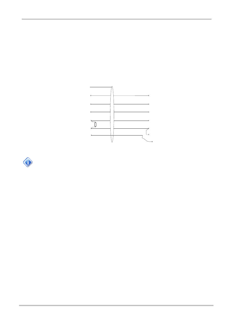
The diagram below shows a typical cable required to enable RS232 telemetry in non-dedicated mode. The
actual modem/radio connections may vary depending on the type of device used. The DSR line from the
modem or radio is used to enable the RS232 port and the RI line enables the binary only mode and sets the
port speed to the one configured in the communications configuration menu.
Figure 12 - Typical RS232 / Data Radio Cable
In this mode, the RS232 telemetry mode is controlled by the cable. If it is unplugged and a
standard null-modem cable connected, the iRIS RS232 port will immediately switch back to
normal port operation, with the usual terminal and binary communications at 38400bps. The
connection icon (house) will always indicate the status of the wireless connection only.
9.3 Gateway Communication
The iRIS supports a powerful communication function - gateway, or redirected communications. Simply put,
this allows an iRIS to transfer packets of data between ports, totally in the background without any
programming required (beyond setting up the gateway offset.)
Uses include:
Radio comms repeater function
IP to radio bridging
When an incoming data packet is received from either communications port, the iRIS does the following:
Is this message for me? If it is, then accept and process it. Gateway redirection is not needed and
no further action is taken.
Check if the iRIS has a gateway offset configured. If it does, then test the destination address in the
received packet and see if it falls in the range covered by the gateway. If a match is found, then the
packet will have its source and destination addresses changed (aliased) and be transmitted. In non-
dedicated mode it will be sent from the other port. In dedicated mode it will be sent from the same
port that the packet was received on.
If the packet has not been used by this point then it is rejected and lost.
Note: All retries are the responsibility of the transmission originator.
The only setup required to use gateway communications is to set the gateway table offset. See Section
4.4.3.
AUX_RXD (IN) 3
AUX_TXD (OUT) 11
0V (SIGNAL) 15
GPIO4 BUSY (OUT) 10
+13V8 (OUT) 8
WHITE
YELLOW
BLACK
BLUE
RED
2 RXD (IN)
3 TXD (OUT)
5 OV (SIGNAL)
8 CTS (IN)
6 DSR (IN)
FRAME GND
Tait TM80xx Radio
DB15 (M)
iRIS Datalogger
DB9 (F)
SCREEN
9 RI (IN)
10K
FLYING LEAD
TO DIG OUT
GPIO6 ENABLE (IN) 9
GREEN