Xylem SDI-12 Data Logger iRIS 220, iRIS 320, iRIS 350, iRIS 150, iRIS 300 User Manual
Page 36
iRIS Datalogger User Guide V1.50
30
iQuest (NZ) Ltd - PO Box 15169, Hamilton, New Zealand Tel: +64 7 857-0810 Fax: +64 7 857-0811 Email: [email protected]
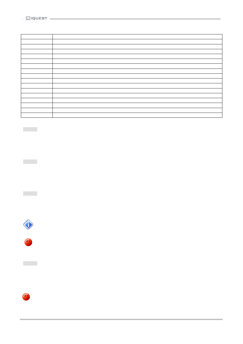
Flag Value
Description
0
No additional logging
1
Log Minimum
2
Log Maximum
3
Log Minimum and Maximum
4
Log Standard Deviation
5
Log Minimum and Standard Deviation
6
Log Maximum and Standard Deviation
7
Log Minimum, Maximum and Standard Deviation
8
Log Flow Rate or Accumulated Volume
9
Log Minimum and Flow Rate or Accumulated Volume
10
Log Maximum and Flow Rate or Accumulated Volume
11
Log Minimum, Maximum and Flow Rate or Accumulated Volume
12
Log Standard Deviation and Flow Rate or Accumulated Volume
13
Log Minimum, Standard Deviation and Flow Rate or Accumulated Volume
14
Log Maximum, Standard Deviation and Flow Rate or Accumulated Volume
15
Log Minimum, Maximum, Standard Deviation and Flow Rate or Accumulated Volume
Table 5 - Supplementary Logging Flag Definitions
Option 4
When this option is selected you will be prompted to enter a scaling multiplier. This multiplier is used to
convert the raw input into engineering units. It is the “m” variable in the y=mx+c scaling equation.
> Multiplier=
Option 5
When this option is selected you will be prompted to enter a scaling offset. This offset is added to the scaled
engineering value. It is the “c” variable in the y=mx+c scaling equation.
> Offset=
Option 6
When this option is selected you will be prompted to enter a logging multiplier to convert from engineering
units to an integer value for storage in the logging memory.
> Log Multiplier=
For example, if you need to log a measurement that has a resolution of two decimal places,
you will need to enter a logging multiplier of 100.
IMPORTANT NOTE: Care needs to be taken in the selection of an appropriate logging
multiplier because the iRIS stores data as signed 16-bit integer values (range from -32768 to
32767). This means that the maximum scaled value multiplied by the logging multiplier must
not exceed 32767. If it does, the values will limit at that point and data will be lost.
Option 7
When this option is selected you will be prompted to enter a logging rate (in minutes) for the sensor.
> Log Rate=
If you wish to log digital data in true event (change of state) mode you can enter a value of 0 for this setting.
If this parameter is left set to 0 for any non-pulse type source, then it will not be logged.