Programming – Xylem IM167 R8 Aquavar CPC (Centrifugal Pump Control) User Manual
Page 96
96
MultiPump – Slave Pump Control
Lead vs. Lag
The Aquavar controlled pump will always be considered the “LEAD “pump, and start first in
the system sequence. The constant speed pumps will always be the “SLAVE “or “LAG “pumps
in the system. When the Aquavar controlled pump, starts to “run out “or cannot meet the
system demand, then the first relay output will actuate based on a programmed pressure and
time delay. The Aquavar CPC has up to three contacts that can be used for “SLAVE” operation.
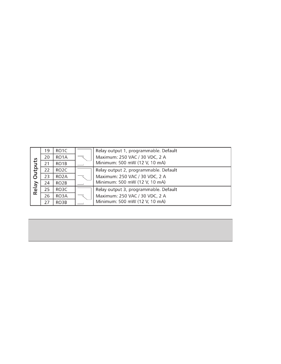
Wiring/ Connection
The relays used for the SLAVE pump control are dry relay contacts, rated for a MAXIMUM
250 VAC or 30VDC, 2 Amps free from inductivity. Minimum is 500 mW (12V, 10mA). Refer to
diagram below, or in APPENDIX section.
Each relay will be wired to a voltage starter DO NOT EXCEED 250 VOLTS AC through each
relay. Each relay is designed for control power only. It is up to the operator to provide
necessary starters, overloads or fuses for each SLAVE pump motor control. Always follow your
local codes or National codes and have a certified electrician perform the necessary wiring.
NOTE: Normally Closed (NC) = R01A, R02A, R03A
Common Connection (CC) = R01C, R02C, R03C
Normally Open (NO) = R01B, R02B, R03B
SLAVE Pump Sizing/ Piping
It is recommended that each slave pump be sized the same and with the same performance
curve. All necessary check valves, ball valves, or gate valves should be installed in the system
to limit or “choke” each SLAVE pump discharge in order to maintain proper head conditions
and to prevent pressure oscillations or system “hunting”. Follow all recommended Hydraulic
Institute standards for piping size and pipe layout.
= Run power to drive
= Ready pump is running
= not used
PROGRAMMING