Programming, Multipump – constant pressure control – Xylem IM167 R8 Aquavar CPC (Centrifugal Pump Control) User Manual
Page 88
88
Terminated
Station
Station
Station
Terminated
Station
X1 Identification
28 Screen
29 B
30 A
31 AGND
32 Screen
SCR
B
A
GND
B
A
GND
SCR
28 SCR
29 B
30 A
31 AGND
32 SCR
ON ON
ON ON
RS485 Multidrop Application
Other Modbus Devices
Hardware Description
1
RS485 Interface
J2 J5
J2 J5
off position on position
Bus Termination
1
For functional descriptions, see “Standard Serial Communication” addendum.
MultiPump – Constant Pressure Control
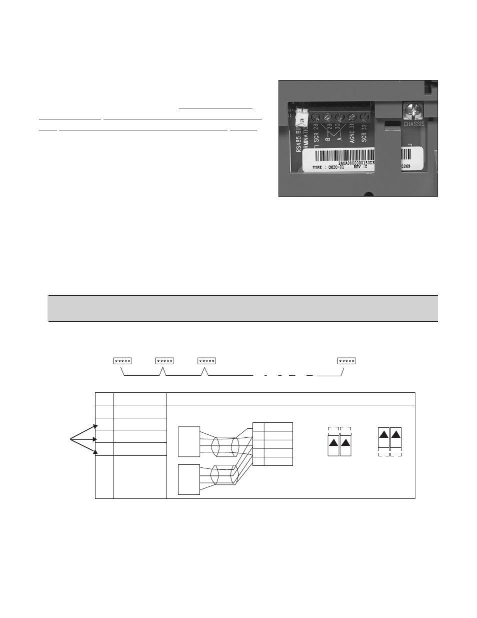
Wiring/Connection RS485
Each Aquavar unit must be connected via terminals
29, 30 and 31. Using a three wire shielded cable
between each Aquavar terminal. Suggested wire
specifications would be 3 or 4 wire, 22AWG, one
pair shielded, TYPE CM or CL3, 75 degree C(UL).
Remember to keep the color coded wires the same
to each terminal connection, and inspect for loose or
bad connections.
When using all the same Aquavar CPC units, you must
provide a BUS TERMINATION for the last drives in the
multi-pump system. The RS485 has two yellow DIP
SWITCHES that must be in the ON position when that Aquavar CPC unit is the last or first in
the system. Therefore, if you have 4 pumps in multi-pump configuration, Aquavar address 1
and Aquavar address 4 would have their DIP SWITCHES in the ON position (see diagram). If
you have a DUPLEX system, then Aquavar address 1 and Aquavar address 2 would have the
switches in the ON position.
Always follow your local codes or National codes and have a certified electrician perform the
necessary wiring.
NOTE: Fieldbus cannot be used with RS485 multipump (Modbus, Devicenet,
Profibus). Single pump only!
Multipump
Connections
for each
Aquavar
PROGRAMMING